


3 - 4
S-100 • S-105 • S-120 • S-125
Part No. 1268494
March 2017
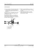
Section 3 • Repair Procedures
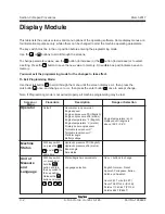
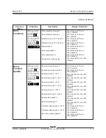
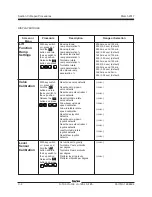
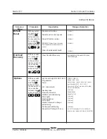
DISPLAY MODULE
Screen or
Menu
Procedure
Description
Range or Selection
Boom up/down
ramp acceleration %
Boom up/down
ramp deceleration %
Boom extend/retract
ramp acceleration %
Turntable rotate
ramp acceleration %
Turntable rotate
ramp deceleration %
Jib up/down ramp
deceleration %
Lift
Function
Ramp
Settings
Valve
Calibration
With key switch
off
, press and
hold the
button and turn
the key switch to
the
on
position.
Release the
button and press
5000 max and 100 min,
5000 (5.0 sec) (default)
2600 max and 100 min,
500 (0.50 sec) (default)
1600 max and 100 min,
500 (0.50 sec) (default)
5000 max and 100 min,
2000 (2.0 sec) (default)
3000 max and 100 min,
250 (0.25 sec) (default)
3000 max and 0 min,
250 (0.25 sec) (default)
With key switch
off
, press and
hold the
button and turn
the key switch to
the
on
position.
Release the
button and press
Reset drive valve defaults
Reset boom up/down
valve defaults
Reset boom extend/retract
valve defaults
Reset turntable rotate
valve defaults
Allow boom up/down
speed calibration
Allow turntable rotate
speed calibration
Reset drive joystick
defaults
Reset boom up/down
joystick defaults
Reset boom extend/retract
joystick defaults
reset turntable rotate
joystick defaults
Reset steer joystick
defaults
Level
Sensor
Calibration
With key switch
off
, press and
hold the
button and turn
the key switch to
the
on
position.
Release the
button and press
Set unit level to gravity
Turntable Y-axis millivolts
per degree
Turntable X-axis millivolts
per degree
Platform level to gravity
Platform millivolts per degree
(
yes
/
no
)
(
yes
/
no
)
(
yes
/
no
)
(
yes
/
no
)
(
yes
/
no
)
(
yes
/
no
)
(
yes
/
no
)
(
yes
/
no
)
(
yes
/
no
)
(
yes
/
no
)
(
yes
/
no
)
(
yes
/
no
)
(
yes
/
no
)
Summary of Contents for S-100
Page 246: ...March 2017 Section 6 Schematics 6 22 Safety Circuit Schematic 6 21 ...
Page 259: ...Section 6 Schematics March 2017 6 35 6 36 Electrical Schematic Generator Options ...
Page 262: ...March 2017 Section 6 Schematics 6 38 6 37 Electrical Schematic 12 kW Generator welder option ...
Page 264: ...March 2017 Section 6 Schematics 6 40 Perkins 1104D 44T Engine Electrical Schematic 6 39 ...
Page 265: ...Section 6 Schematics March 2017 6 41 Perkins 854F 34T Engine Electrical Schematic 6 42 ...
Page 268: ...March 2017 Section 6 Schematics 6 44 Perkins 854F 34T Engine Harness 6 45 ...
Page 269: ...Section 6 Schematics March 2017 6 45 Deutz TD2011L04i Engine Electrical Schematic 6 46 ...
Page 271: ...Section 6 Schematics March 2017 6 47 Deutz TD2 9 Engine Electrical Schematic 6 48 ...
Page 274: ...March 2017 Section 6 Schematics 6 50 Deutz TD2 9 Engine Electrical Harness 6 51 ...
Page 276: ...March 2017 Section 6 Schematics 6 52 6 53 Hydraulic Schematic 12 kW Generator welder option ...


