


Part No. 1268494
S-100 • S-105 • S-120 • S-125
3 - 115
March 2017
Section 3 • Repair Procedures
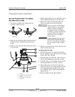
MANIFOLDS
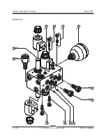
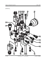
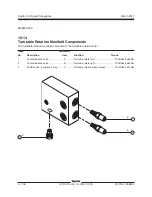
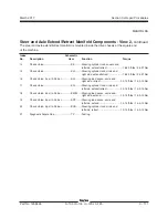
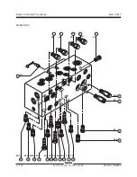
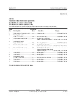
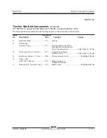
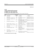
10-18
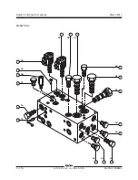
Traction Manifold Components
(S-100/105- to serial number 290)
(S-120/125- to serial number 1194)
The drive manifold is mounted inside the drive chassis at the circle end of the machine.
Index
Schematic
No.
Description
Item
Function
Torque
1
Solenoid valve, 2 position 3 way
........ DA ..........2 speed control .........................................
25-30 ft-lbs / 38-41 Nm
2
Flow regulator valve,
2 gpm / 7.57 L/min
............................. DB ..........Drive slip limit, rear ...................................
35-40 ft-lbs / 47-54 Nm
3
Flow divider/combiner valve
...............
DC
..........
Controls flow to rear drive
motors in forward and reverse ....
130-140 ft-lbs / 176-190 Nm
4
Flow regulator valve,
2 gpm / 7.57 L/min
............................. DD ..........Drive slip limit, front ..................................
35-40 ft-lbs / 47-54 Nm
5
Flow divider/combiner valve
............... DE ..........
Controls flow to front drive
motors in forward and reverse ....
130-140 ft-lbs / 176-190 Nm
6
Flow divider/combiner valve ............... DF ..........
Controls flow to front and
rear flow divider combiner valves
(items DC and DE)
.....................
130-140 ft-lbs / 176-190 Nm
7
Check valve
........................................ DG .........Anti-cavitation ...........................................
35-40 ft-lbs / 47-54 Nm
8
Check valve
........................................ DH ..........Anti-cavitation ...........................................
35-40 ft-lbs / 47-54 Nm
9
Flow regulator valve,
2.7 gpm / 10.22 L/min ........................ DI ...........Drive slip limit, front and rear ....................
35-40 ft-lbs / 47-54 Nm
10
Check valve
........................................ DJ ..........Anti-cavitation ...........................................
35-40 ft-lbs / 47-54 Nm
11
Check valve
........................................
DK
..........Anti-cavitation ...........................................
35-40 ft-lbs / 47-54 Nm
This list continues. Please turn the page.
Summary of Contents for S-100
Page 246: ...March 2017 Section 6 Schematics 6 22 Safety Circuit Schematic 6 21 ...
Page 259: ...Section 6 Schematics March 2017 6 35 6 36 Electrical Schematic Generator Options ...
Page 262: ...March 2017 Section 6 Schematics 6 38 6 37 Electrical Schematic 12 kW Generator welder option ...
Page 264: ...March 2017 Section 6 Schematics 6 40 Perkins 1104D 44T Engine Electrical Schematic 6 39 ...
Page 265: ...Section 6 Schematics March 2017 6 41 Perkins 854F 34T Engine Electrical Schematic 6 42 ...
Page 268: ...March 2017 Section 6 Schematics 6 44 Perkins 854F 34T Engine Harness 6 45 ...
Page 269: ...Section 6 Schematics March 2017 6 45 Deutz TD2011L04i Engine Electrical Schematic 6 46 ...
Page 271: ...Section 6 Schematics March 2017 6 47 Deutz TD2 9 Engine Electrical Schematic 6 48 ...
Page 274: ...March 2017 Section 6 Schematics 6 50 Deutz TD2 9 Engine Electrical Harness 6 51 ...
Page 276: ...March 2017 Section 6 Schematics 6 52 6 53 Hydraulic Schematic 12 kW Generator welder option ...


