


3 - 124
S-100 • S-105 • S-120 • S-125
Part No. 1268494
March 2017
Section 3 • Repair Procedures
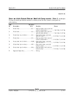
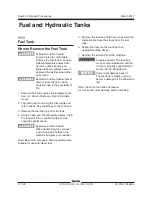
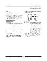
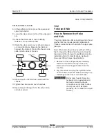
Valve Coil Resistance
Specification
Note: The following coil resistance specifications
are at an ambient temperature of 68°F / 20°C. As
valve coil resistance is sensitive to changes in
air temperature, the coil resistance will typically
increase or decrease by 4% for each 18°F / 20°C
that your air temperature increases or decreases
from 68°F / 20°C.
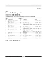
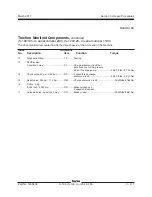
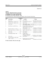
Description
Specification
Solenoid valve, 2 position 3 way, 12V DC
9
Ω
(schematic item DA, DO, FB, FC)
Solenoid valve, 3 position 4 way, 12V DC
9.8
Ω
(schematic item EA, EB, EC, ED)
(before serial number 292)
Solenoid valve, 3 position 4 way, 12V DC
8.8
Ω
(schematic item EA, EB, EC, ED)
(after serial number 291)
Proportional solenoid valve, 12V DC
5.4
Ω
(schematic item FG, BG, GD, GH)
Proportional solenoid valve, 12V DC
5
Ω
(schematic item FB, FF, BB, BF)
3 position 4 way D03 valve, 12V DC
4.6
Ω
(schematic item FD, BD)
Solenoid Valve, 2 position 3 way, 12V DC
4.6
Ω
(schematic item FQ, FR, BQ, BR)
Solenoid Valve, 2 position 2 way, 12V DC
7.2
Ω
(schematic item BN, BO)
Solenoid valve, 3 position 4 way 12V
7.2
Ω
(schematic items ES, FC, BC)
(before serial number 292)
Solenoid valve, 3 position 4 way 12V
7.1
Ω
(schematic items ES)
(after serial number 291)
Solenoid valve, 2 position 3 way 12V
7.2
Ω
(schematic items AA)
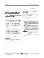
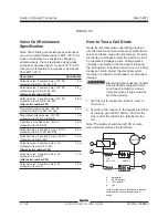
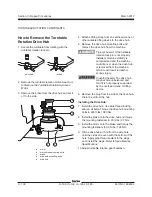
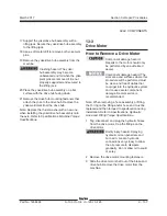
How to Test a Coil Diode
Genie incorporates spike suppressing diodes in
all of its directional valve coils except proportional
valves and those coils with a metal case. Properly
functioning coil diodes protect the electrical circuit
by suppressing voltage spikes. Voltage spikes
naturally occur within a function circuit following
the interruption of electrical current to a coil. Faulty
diodes can fail to protect the electrical system,
resulting in a tripped circuit breaker or component
damage.
Electrocution/burn hazard. Contact
with electrically charged circuits
could result in death or serious
injury. Remove all rings, watches
and other jewelry.
1 Test the coil for resistance. Refer to,
How to
Test a Coil.
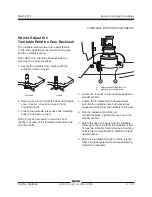
2 Connect a 10
Ω
resistor to the negative terminal
of a known good 9V DC battery. Connect the
other end of the resistor to a terminal on the
coil.
Note: The battery should read 9V DC or more
when measured across the terminals.
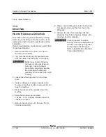
9V
BATTERY
10
RESISTOR
AMMETER
COIL
+
-
+
-
d
a
b
b
c
c
a multimeter
b
9V DC battery
c 10
Ω
resistor
d coil
Note: Dotted lines in illustration indicate a
reversed connection as specified in
step 6
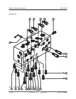
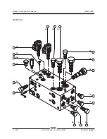
MANIFOLDS
Summary of Contents for S-100
Page 246: ...March 2017 Section 6 Schematics 6 22 Safety Circuit Schematic 6 21 ...
Page 259: ...Section 6 Schematics March 2017 6 35 6 36 Electrical Schematic Generator Options ...
Page 262: ...March 2017 Section 6 Schematics 6 38 6 37 Electrical Schematic 12 kW Generator welder option ...
Page 264: ...March 2017 Section 6 Schematics 6 40 Perkins 1104D 44T Engine Electrical Schematic 6 39 ...
Page 265: ...Section 6 Schematics March 2017 6 41 Perkins 854F 34T Engine Electrical Schematic 6 42 ...
Page 268: ...March 2017 Section 6 Schematics 6 44 Perkins 854F 34T Engine Harness 6 45 ...
Page 269: ...Section 6 Schematics March 2017 6 45 Deutz TD2011L04i Engine Electrical Schematic 6 46 ...
Page 271: ...Section 6 Schematics March 2017 6 47 Deutz TD2 9 Engine Electrical Schematic 6 48 ...
Page 274: ...March 2017 Section 6 Schematics 6 50 Deutz TD2 9 Engine Electrical Harness 6 51 ...
Page 276: ...March 2017 Section 6 Schematics 6 52 6 53 Hydraulic Schematic 12 kW Generator welder option ...


