


Part No. 1268494
S-100 • S-105 • S-120 • S-125
3 - 53
March 2017
Section 3 • Repair Procedures
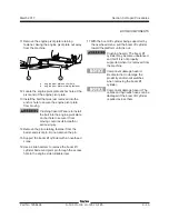
20 Secure the number 2 and number 3 booms
together at the platform end with a chain or
strap to prevent them from moving.
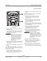
21 Install the boom extension cylinder assembly
into the boom.
Note: Before lowering the extension cylinder into
the saddles of the number 1 boom tube, wrap the
boom retract cables around the pulleys.
22 Remove the chain or strap from the platform
end of the number 2 and number 3 boom tubes.
23 Adjust the boom extend/retract cables.
See,
How to Adjust the Boom Extend/Retract
Cables.
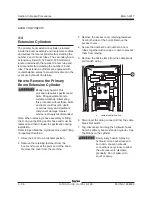
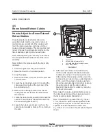
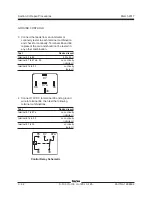
Boom retract cables:
9 Remove the fasteners from the boom retract
cables at the platform end of the boom.
10 Attach a rope to one of the boom retract cables
at the pivot end of the boom.
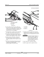
11 At the platform end of the boom, pull on the
boom retract cable that has the rope attached
to it.
12 Pull the old cable completely out of the boom
tube. Discard the old boom retract cable.
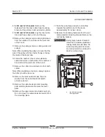
13 Remove the rope from the old cable and
securely attach the rope to the same end of the
new boom retract cable.
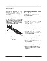
14 At the pivot end of the boom, carefully pull the
rope with the new retract cable attached.
15 Pull the new cable towards the pivot end of the
boom until the end of the cable is at the end of
the boom tube. Remove the rope.
16 Repeat steps 11 through 16 for the other boom
retract cable.
17 At the platform end of the boom, install the
retract cables and fasteners to the adjustment
plate.
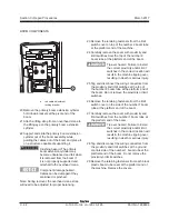
18 Remove and discard the old boom retract
pulleys from the pivot end of the boom
extension cylinder.
19 Install the new boom retract pulleys to the pivot
end of the boom extension cylinder.
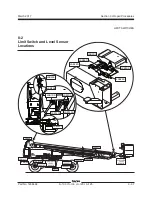
BOOM COMPONENTS
Summary of Contents for S-100
Page 246: ...March 2017 Section 6 Schematics 6 22 Safety Circuit Schematic 6 21 ...
Page 259: ...Section 6 Schematics March 2017 6 35 6 36 Electrical Schematic Generator Options ...
Page 262: ...March 2017 Section 6 Schematics 6 38 6 37 Electrical Schematic 12 kW Generator welder option ...
Page 264: ...March 2017 Section 6 Schematics 6 40 Perkins 1104D 44T Engine Electrical Schematic 6 39 ...
Page 265: ...Section 6 Schematics March 2017 6 41 Perkins 854F 34T Engine Electrical Schematic 6 42 ...
Page 268: ...March 2017 Section 6 Schematics 6 44 Perkins 854F 34T Engine Harness 6 45 ...
Page 269: ...Section 6 Schematics March 2017 6 45 Deutz TD2011L04i Engine Electrical Schematic 6 46 ...
Page 271: ...Section 6 Schematics March 2017 6 47 Deutz TD2 9 Engine Electrical Schematic 6 48 ...
Page 274: ...March 2017 Section 6 Schematics 6 50 Deutz TD2 9 Engine Electrical Harness 6 51 ...
Page 276: ...March 2017 Section 6 Schematics 6 52 6 53 Hydraulic Schematic 12 kW Generator welder option ...