1-10
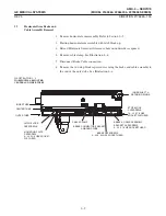
9. Measure and record the horizontal A & B distances, in inches, between the x-
ray field and the light field. See Illustration 1-7.
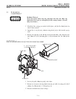
10. Measure and record the vertical C & D distances, in inches, between the x-ray
field and the light field. See Illustration 1-6.
11. The total of the horizontal differences as well as the total of the vertical differĆ
ences must each be less than 1.8% of the SID:
D
A + B < 1.8% SID = A + B <0 .018
40 inches = A + B < 0.72 inches
D
C + D < 1.8% SID = C + D <0 .018
40 inches = C + D < 0.72 inches
If the above requirements are met, go to step 18. If they are not met, proceed with
the following steps.
Ideally, the x-ray field and the light field should coincide but this is rarely the
case. The best compromise is to move the light field so the x-ray field is cenĆ
tered within it. Usually the light field area will be larger than the x-ray area.
12. To place the two fields as close to coincidence as possible, only the light field area
is moved. The light field area adjustment is made by repositioning the field lamp
housing.
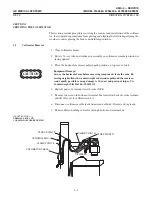
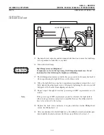
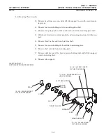
13. Loosen the two Phillips head adjustment screws located in the back of the colliĆ
mator. See Illustration 1-8.
14. Examine the last exposure and determine which direction to move the field lamp
to best position light field around the x-ray field.
15. Turn on the field lamp.
ILLUSTRATION 1-8
Summary of Contents for AMX 4+
Page 1: ...0 0 1 1 2 2...
Page 2: ......
Page 3: ...D D D D D D D D D D D D D D D D...
Page 4: ...D D D D D D D D...
Page 6: ...iv...
Page 8: ...vi...
Page 14: ...xii...
Page 18: ...xvi...
Page 32: ...1 14...
Page 48: ...3 14...
Page 84: ...5 10...
Page 106: ...7 12...
Page 112: ...8 6...
Page 116: ...9 4...
Page 131: ......
Page 132: ...3 2 2 1 0 3 5 0 2 0 4 0 2...


