


6-2
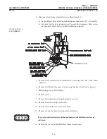
2. Verify that AMX key switch is OFF, circuit breaker is OFF, and charger cord is
unplugged.
3. Remove battery ground cable marked #2 from the ground stud. Tape to ensure
it does not short. SEPARATE IT FROM ALL OTHER CABLES.
All battery lead connectors must be insulated to prevent electrical contact
with the frame or other battery terminals.
4. Tape cable marked #5 separately from ALL other cables.
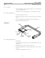
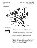
5. Remove all remaining cables from ground stud. See Illustration 6-1. Tape each
cable separately. Keep ALL cables separate.
6. Remove battery lead cable marked #4 from terminal on Circuit Breaker in
AMX1 A3 Module. Be certain boot covers the connector and it cannot short out.
Tape connector to ensure it will not short.
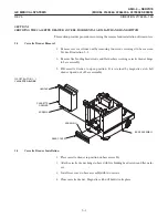
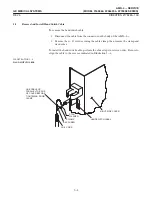
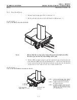
7. Remove battery compartment cover capscrews and cover.
8. Remove insulator board from compartment entrance.
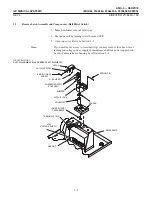
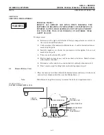
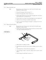
1. If unit has a battery sense harness, disconnect harness from J11 of the battery test
terminal strip. See Illustration 6-2.
2. Disconnect sense leads from J9 and J10 on left hand side of the battery test termiĆ
nal strip.
Summary of Contents for AMX 4+
Page 1: ...0 0 1 1 2 2...
Page 2: ......
Page 3: ...D D D D D D D D D D D D D D D D...
Page 4: ...D D D D D D D D...
Page 6: ...iv...
Page 8: ...vi...
Page 14: ...xii...
Page 18: ...xvi...
Page 32: ...1 14...
Page 48: ...3 14...
Page 84: ...5 10...
Page 106: ...7 12...
Page 112: ...8 6...
Page 116: ...9 4...
Page 131: ......
Page 132: ...3 2 2 1 0 3 5 0 2 0 4 0 2...


