5-7
'
!" " !!& "! " %"
1. Shut off power by turning circuit breaker OFF.
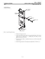
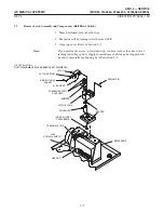
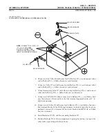
2. Install solenoid in recess in latch block. See Illustration 5-4.
3. Install hex nut on top ofsolenoid.
! " $ " !"" ! " " " !! '
#"
4. Install Hall effect sensor circuit board and cover with two flat head screws.
5. Attach latch spring to latch with binding head screw.
6. Install latch in latch block.
7. Insert spring pin in latch block to retain latch in position.
8. Install latch block on spacer and fasten with four hex socket head capscrews.
9. Install latch assembly on mainframe and fasten with four hex socket head
capscrews.
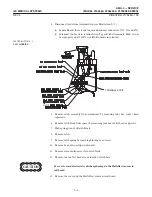
10. Connect leads from latch assembly:
D
Hall Effect Sensor Board: three leads to terminal strip #1, #2 and #3.
D
Solenoid: two leads to terminal strip in accordance with labels on terminals.
11. Ifyou moved low voltage power supply out ofthe way in Section 5Ć7, slide power
supply onto mainframe housing and fasten with four hex nuts.
12. Close top cover. Refer to Section 5-6.
Summary of Contents for AMX 4+
Page 1: ...0 0 1 1 2 2...
Page 2: ......
Page 3: ...D D D D D D D D D D D D D D D D...
Page 4: ...D D D D D D D D...
Page 6: ...iv...
Page 8: ...vi...
Page 14: ...xii...
Page 18: ...xvi...
Page 32: ...1 14...
Page 48: ...3 14...
Page 84: ...5 10...
Page 106: ...7 12...
Page 112: ...8 6...
Page 116: ...9 4...
Page 131: ......
Page 132: ...3 2 2 1 0 3 5 0 2 0 4 0 2...


