


REV5
DIRECTION 2173225-100
5-2
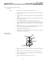
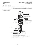
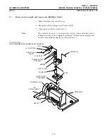
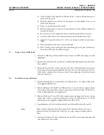
This procedure covers the removal of both the right and left trim covers.
1. Turn power off by turning circuit breaker OFF.
2. Remove front cover from unit by pulling corners of cover from ball stud retainer
sockets on mainframe. See Illustration 5-2.
3. Remove rear cover by removing two screws retaining it on base assembly.
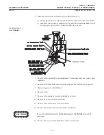
4. Disconnect hand switch on right side trim cover.
5. Remove two 4-40 x 3/8 inchbinding head screws and one 6-32 x 1/2 inchblack
oxide binding head screw holding each cover to base and mainframe assemblies.
6. Pull covers loose from five ball stud retaining sockets and carefully remove from
unit.
ILLUSTRATION 5-2
BALL STUDS
BALL STUDS
FRONT COVER
HAND SWITCH
4-40 x 3/8
SCREWS
RIGHT COVER
LEFT COVER
BATTERY COMPARTMENT COVER
SCREWS TOP AND BOTTOM
6-32 X 1/2 BLACK
OXIDE SCREW
6-32 X 1/2 BLACK
OXIDE SCREW
4-40 x 3/8
SCREWS
Summary of Contents for AMX 4+
Page 1: ...0 0 1 1 2 2...
Page 2: ......
Page 3: ...D D D D D D D D D D D D D D D D...
Page 4: ...D D D D D D D D...
Page 6: ...iv...
Page 8: ...vi...
Page 14: ...xii...
Page 18: ...xvi...
Page 32: ...1 14...
Page 48: ...3 14...
Page 84: ...5 10...
Page 106: ...7 12...
Page 112: ...8 6...
Page 116: ...9 4...
Page 131: ......
Page 132: ...3 2 2 1 0 3 5 0 2 0 4 0 2...


