3-8
3Ć6
Horizontal Arm
Assembly Installation
Note:
The counterweight must be at the bottom of the column or otherwise immobiĆ
lized.
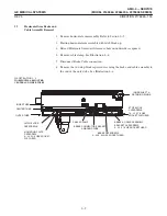
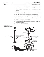
1. Mount horizontal arm assembly on carriage assembly flanges. See Illustration
3-5.
2. While supporting the arm, secure it firmly in place with six mounting screws.
Torque to 110 pound-inches (12.3 N-m).
3. Route brake cable along the anode cable to strap point on side of the column.
Secure brake cable to the anode cable with ty-raps.
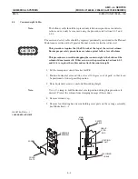
4. Drape the cable from the side of the column to the terminal box on the back of
the column. Insert the brake cable with a Heyco bushing up through the bottom
of the terminal box.
5. Connect brake cable leads to terminal block in accordance with connection data
recordedandtaggedon leads.
6. Position back cover on terminal box andsecure with two screws.
Equipment Damage!
The horizontal arm must be secured before installingcomponents on the
arm. Do not rely on latch alone to hold it in place. With weight removed from
the arm, the counterweight can descend rapidly and the arm ascend rapidly
possibly causing damage to the unit and personal injury. Use Counterweight
Lift Tool 46-303491G1.
7. Firmly grasp the horizontal arm andusing your weight to counterbalance the
counterweight, approximately 75 pounds (34 kg), carefully move it down to the
top of the unit andinto parkedposition. Do not rely on latch alone to holdthe
arm in place. Check that the arm is lockeddown before slowly removing your
weight andreleasing it.
8. ReĆmount the x-ray tube andcollimator assembly per Illustration 3-4.
9. Check that the arm moves freely up anddown the column.
CAUTION
Summary of Contents for AMX 4+
Page 1: ...0 0 1 1 2 2...
Page 2: ......
Page 3: ...D D D D D D D D D D D D D D D D...
Page 4: ...D D D D D D D D...
Page 6: ...iv...
Page 8: ...vi...
Page 14: ...xii...
Page 18: ...xvi...
Page 32: ...1 14...
Page 48: ...3 14...
Page 84: ...5 10...
Page 106: ...7 12...
Page 112: ...8 6...
Page 116: ...9 4...
Page 131: ......
Page 132: ...3 2 2 1 0 3 5 0 2 0 4 0 2...


