


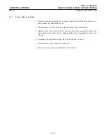


5-4
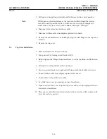
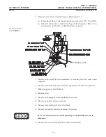
5. Lift top cover straight up until right and left hinges lock in vertical position.
With top cover extended on hinges, the cover can be tilted toward the front or
rear of the unit to provide access to either area for servicing. If complete reĆ
moval of the cover is necessary then continue with steps 5 through 9.
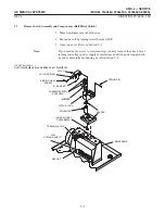
6. Disconnect wires from key switch assembly.
7. Disconnect ribbon cable from display at printed wire board.
8. Remove the shouldered screws holding the right and left hinges to the top cover
brackets.
9. Removethetop cover.
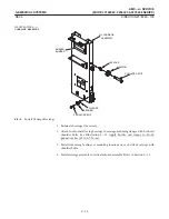
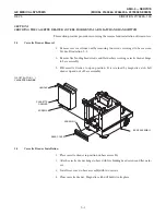
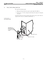
1. Movehorizontal arm to top of column.
2. Turn power off by turning circuit breaker OFF.
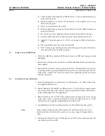
3. Extend right and left hinges from mainframe to vertical position. See Illustration
5-3.
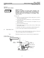
4. Lift top cover and position brackets on hinges.
5. Secure top cover brackets to right and left hinges with two shouldered screws.
6. Connect ribbon cable from display to printed wire board.
7. Connect wires to key switch assembly.
8. Carefully lower cover into position on top of mainframe.
9. Open cassette drawer, reach up into top cover and rotate two spring latches to
lock cover to mainframe.
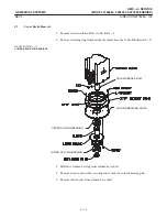
10. Place spacer and collar on horizontal arm latch and secure collar in place with
three hex socket capscrews.
Summary of Contents for AMX 4+
Page 1: ...0 0 1 1 2 2...
Page 2: ......
Page 3: ...D D D D D D D D D D D D D D D D...
Page 4: ...D D D D D D D D...
Page 6: ...iv...
Page 8: ...vi...
Page 14: ...xii...
Page 18: ...xvi...
Page 32: ...1 14...
Page 48: ...3 14...
Page 84: ...5 10...
Page 106: ...7 12...
Page 112: ...8 6...
Page 116: ...9 4...
Page 131: ......
Page 132: ...3 2 2 1 0 3 5 0 2 0 4 0 2...


