4-3
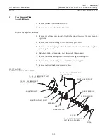
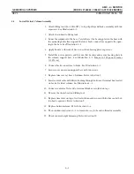
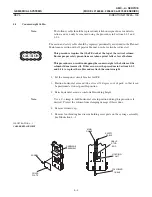
1. Attach liftingtool (46-303362P1) to top of pulley and brake assembly with two
capscrews. See Illustration 4-2.
2. Attach chain hoist to liftingtool.
3. Lower the column into the base. Carefully seat the bearingplate in the base with
the mountingholes lined up and the lower brake connectors opposite the openĆ
ingin the base. See Illustration 4-2.
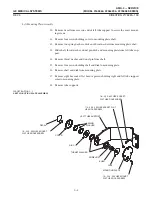
4. Apply Loctite to threads of five new column bearingplate capscrews.
5. Install five new capscrews and five new flat washers and secure bearingplate to
the column support base. See Illustration 4-2. Torque to 100 pound-inches
(11.3 N-m).
6. Connect brake connectors to brake. See Illustration 4-2.
7. Secure cover on column support base with two screws.
8. Replace trim cover at base of column. Refer to Section 5.
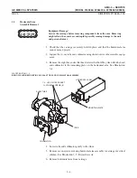
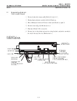
9. Insert control cable with Heyco bushingthrough bottom of terminal box located
on back of vertical column. See Illustration 4-1.
10. Connect control cable leads to terminal block as recorded on tags.
11. Remove the chain hoist and liftingtool.
12. Replace trim cover on top of vertical column and secure with two hex socket butĆ
ton head capscrews. Refer to Section 5.
13. Replace horizontal arm. Refer to Section 3-6.
14. Then continue in Section 3-6 to remount x-ray tube and collimator assembly.
15. Check counterweight balancing. Refer to Section 10.
Summary of Contents for AMX 4+
Page 1: ...0 0 1 1 2 2...
Page 2: ......
Page 3: ...D D D D D D D D D D D D D D D D...
Page 4: ...D D D D D D D D...
Page 6: ...iv...
Page 8: ...vi...
Page 14: ...xii...
Page 18: ...xvi...
Page 32: ...1 14...
Page 48: ...3 14...
Page 84: ...5 10...
Page 106: ...7 12...
Page 112: ...8 6...
Page 116: ...9 4...
Page 131: ......
Page 132: ...3 2 2 1 0 3 5 0 2 0 4 0 2...

