4-1
This section provides procedures covering the removal and installation of the field
serviceable assemblies subassemblies andparts comprising the vertical column assemĆ
bly.
"
!
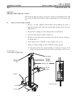
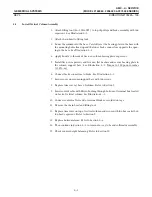
1. Remove x-ray tube, collimator, andhorizontal arm assemblies per Section 3-5.
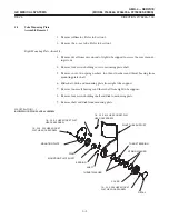
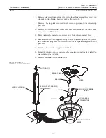
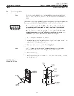
2. Disconnect control cable leads from terminal block. Recordandtag leads. See
Illustration 4-1.
3. Remove Heyco bushing andcable through bottom of terminal box.
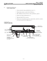
4. Clear all cables andwires from the column area.
5. Remove vertical column cap by removing two hex socket button headcapscrews.
See Illustration 4-1.
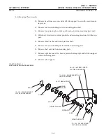
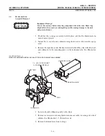
6. Attach lifting tool (46-303362P1) to top of column with 2 screws.
7. Attach chain hoist to lifting tool (46-303362P1) andtake up slack.
D
The chain hoist must be capable of lifting a seven foot (2.1 meter), 175 lb.
(80 kg) column a minimum of two feet (61 cm), preferably 4 feet (122 cm)..
ILLUSTRATION 4-1
Summary of Contents for AMX 4+
Page 1: ...0 0 1 1 2 2...
Page 2: ......
Page 3: ...D D D D D D D D D D D D D D D D...
Page 4: ...D D D D D D D D...
Page 6: ...iv...
Page 8: ...vi...
Page 14: ...xii...
Page 18: ...xvi...
Page 32: ...1 14...
Page 48: ...3 14...
Page 84: ...5 10...
Page 106: ...7 12...
Page 112: ...8 6...
Page 116: ...9 4...
Page 131: ......
Page 132: ...3 2 2 1 0 3 5 0 2 0 4 0 2...


