5-6
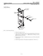
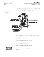
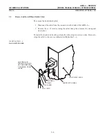
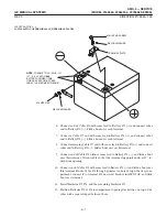
4. Disconnect leads from terminal strip (see Illustration 5-5):
D
Sensor Board: three leads to quick disconnect connectors. (#1, #2 and #3).
D
Solenoid: two leads to terminal strip. Tag and label terminals. Must reconĆ
nect properly on #3 & #4 or will blow diode in solenoid.
ILLUSTRATION 5-5
TERMINAL STRIP
WHITE
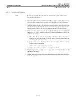
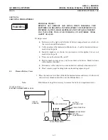
5. Remove latch assembly from mainframe by removing four hex socket head
capscrews.
6. Remove latch block from spacer by removing four hex socket head capscrews.
7. Push spring pin out of latch block.
8. Remove latch.
9. Remove latch spring by removing binding head screw.
10. Remove hex nut from top of solenoid.
11. Remove solenoid from recess in latch block.
12. Remove the two flat head screws in side of latch base.
!
13. Remove the cover and the Hall effect sensor circuit board.
Summary of Contents for AMX 4+
Page 1: ...0 0 1 1 2 2...
Page 2: ......
Page 3: ...D D D D D D D D D D D D D D D D...
Page 4: ...D D D D D D D D...
Page 6: ...iv...
Page 8: ...vi...
Page 14: ...xii...
Page 18: ...xvi...
Page 32: ...1 14...
Page 48: ...3 14...
Page 84: ...5 10...
Page 106: ...7 12...
Page 112: ...8 6...
Page 116: ...9 4...
Page 131: ......
Page 132: ...3 2 2 1 0 3 5 0 2 0 4 0 2...

