


6-9
$
! !!# ! !
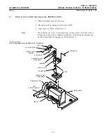
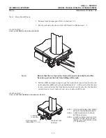
1. Connect Cable #1 Sense Lead (from Battery #8 [+]) to J8 (LHS).
2. Connect Cable #3 Sense Lead (from Battery #7 [+]) to J7 (LHS).
$
!" !!# !!!
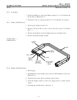
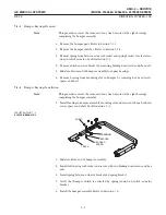
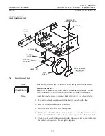
1. Install another Insulator #1 between Batteries #7 and #8 and Battery #9, with
cup-shaped bumps pointing away from you. Route free end of Cable #5 over
the top of this Insulator #1.
2. Install Insulator #8.
3. Position Battery #9 on top of Insulator #8.
4. Connect free end of Cable #5 from Battery #8 [-]to Battery #9 (+), and slide
a boot over terminal.
5. Tape the end of Cable #2 that does not have the sense lead to prevent it from
shorting after it is connected to Battery #9.
6. Connect other end of Cable #2 to Battery #9 (-), and slide a boot over cable
terminal. Route Cable #2 through grommet in hole in top of battery compartĆ
ment.
!
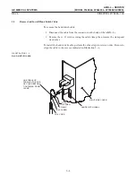
! # " ! ! " !" #!
$
! !!# ! !
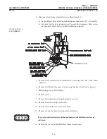
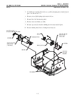
1. Connect Cable #5 Sense Lead (from Battery #9 [+]) to J9 (LHS).
2. Connect Cable #2 Sense Lead (from Battery #9 [-]) to J10 (LHS).
$
! !!# !!!
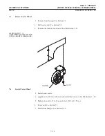
1. Measure the battery voltage between circuit breaker lead marked #6 and the
ground stud. It should measure between 111 and 118 volts DC, depending upon
state of charge of the batteries. If it does not, determine the cause of the problem.
2. If unit has a battery sense harness, connect battery sense harness to the battery
terminal test strip connector J11. See Illustration 6-2.
Summary of Contents for AMX 4+
Page 1: ...0 0 1 1 2 2...
Page 2: ......
Page 3: ...D D D D D D D D D D D D D D D D...
Page 4: ...D D D D D D D D...
Page 6: ...iv...
Page 8: ...vi...
Page 14: ...xii...
Page 18: ...xvi...
Page 32: ...1 14...
Page 48: ...3 14...
Page 84: ...5 10...
Page 106: ...7 12...
Page 112: ...8 6...
Page 116: ...9 4...
Page 131: ......
Page 132: ...3 2 2 1 0 3 5 0 2 0 4 0 2...


