


REV 5
DIRECTION 2173225-100
6-3
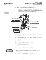
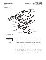
ILLUSTRATION 6-2
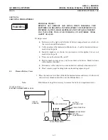
PRINTED WIRING BD ASM
46-321370G1
(J4)
(J3)
(J9)
(J7)
(J10)
(J5)
(J6)
(J8)
(J1)
(J2)
CABLE #4
SENSE LEAD
CABLE #7
SENSE LEAD
CABLE #1
SENSE LEAD
CABLE #6
SENSE LEAD
CABLE #3
SENSE LEAD
CABLE #7
SENSE LEAD
CABLE #2
SENSE LEAD
CABLE #5
SENSE LEAD
CABLE #8
SENSE LEAD
CABLE #1
SENSE
LEAD
BATTERY SENSE
HARNESS
(IF PRESENT)
CONNECTSTO J11
(J11)
'
$"!!% ! "& %%#$
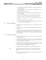
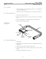
1. Disconnect Cable #2 from Battery #9 (-) and slide boot over cable terminal.
See Illustration 6-3.
2. Disconnect Cable #5 from Battery #9 (+), and slide boot over cable terminal.
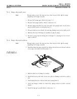
3. Remove Battery #9, Insulator #8, and Insulator #1 in front of Batteries #7 and
#8.
4. Disconnect sense leads from J7 and J8 on left side of battery test terminal strip.
5. Disconnect Cable #3 from Battery #7 (+) and slide boot over cable terminal.
6. Disconnect Cable #5 from Battery #8 (-) and slide boot over cable terminal.
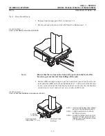
7. Disconnect one of the Cable #1s from Battery #7 (-) and Battery #8 (+), and
slide a boot over each cable terminal.
8. Remove Batteries #7 and #8 and the separator pad between them.
9. Remove the remaining Insulator #1.
Summary of Contents for AMX 4+
Page 1: ...0 0 1 1 2 2...
Page 2: ......
Page 3: ...D D D D D D D D D D D D D D D D...
Page 4: ...D D D D D D D D...
Page 6: ...iv...
Page 8: ...vi...
Page 14: ...xii...
Page 18: ...xvi...
Page 32: ...1 14...
Page 48: ...3 14...
Page 84: ...5 10...
Page 106: ...7 12...
Page 112: ...8 6...
Page 116: ...9 4...
Page 131: ......
Page 132: ...3 2 2 1 0 3 5 0 2 0 4 0 2...


