


REV 5
DIRECTION 2173225-100
6-1
During removal:
D
Reference to the right and left sides of battery compartment are relative to
the view shown in Illustration 4.
D
Cable numbers (#s) indicated in Illustration 6-3 and in this instruction are
marked on the parts.
D
Insulator numbers are shown for convenience in description, but are not
marked on the parts.
D
There are no Insulators #3 and #7.
D
Battery numbers may or may not be marked on batteries. Mark batteries
with numbers if desired.
D
Disconnect cables only in the order instructed, and only when instructed.
D
Don't remove paper backing from any insulating separator pad.
(
!"#&! %%!$' #&!$
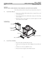
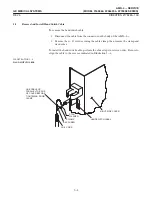
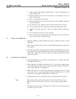
1. Place the unit on a level floor. Extend the horizontal arm and rotate it to the front
end (vertical column end) of the unit. See Illustration 6-1.
#%!
Distribution of weight is necessary to remove the battery compartment cover.
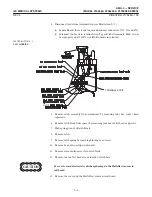
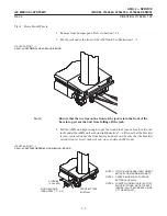
ILLUSTRATION 6-1
COVER CAPSCREWS
CABLE MARKED #4
BATTERY
GROUND STUD
BASE ASSEMBLY
BATTERY
COMPARTMENT
CABLE MARKED #2
CIRCUIT
BREAKER
Summary of Contents for AMX 4+
Page 1: ...0 0 1 1 2 2...
Page 2: ......
Page 3: ...D D D D D D D D D D D D D D D D...
Page 4: ...D D D D D D D D...
Page 6: ...iv...
Page 8: ...vi...
Page 14: ...xii...
Page 18: ...xvi...
Page 32: ...1 14...
Page 48: ...3 14...
Page 84: ...5 10...
Page 106: ...7 12...
Page 112: ...8 6...
Page 116: ...9 4...
Page 131: ......
Page 132: ...3 2 2 1 0 3 5 0 2 0 4 0 2...


