7-8
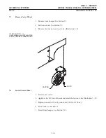
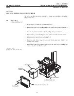
6. Slide the support angle with its wheel block onto the wheel axle as far as it will
go.
7. Tighten the four locknuts and flat washers holding the wheel support angle to the
base assembly. Torque to 50-70 pound-inches (5.6 to 7.8 N-m).
8. Secure the wheel and caliper assembly to the wheel mounting support. Torque
to 40-60 pound-inches (4.5 to 6.7 N-m).
9. Install splash guard and secure with two lock nuts.
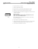
10. Install the motor and brake assembly. Refer to Section 6-10.
11. Lower theunit to thefloor.
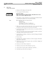
This procedure covers the removal of either the right or left motor and brake
assembly.
1. Move unit to a flat, level surface.
2. Shut off power.
3. Remove cassette drawer from unit. Refer to Section 5-1.
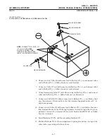
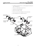
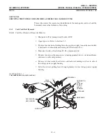
4. Disconnect motor and brake wire connectors from motor control panel. See IlĆ
lustration 7-8.
ILLUSTRATION 7-8
TY–RAPS
CONNECTOR WIRES TO MOTOR CONTROL PANEL
BRAKE
MOTOR
Summary of Contents for AMX 4+
Page 1: ...0 0 1 1 2 2...
Page 2: ......
Page 3: ...D D D D D D D D D D D D D D D D...
Page 4: ...D D D D D D D D...
Page 6: ...iv...
Page 8: ...vi...
Page 14: ...xii...
Page 18: ...xvi...
Page 32: ...1 14...
Page 48: ...3 14...
Page 84: ...5 10...
Page 106: ...7 12...
Page 112: ...8 6...
Page 116: ...9 4...
Page 131: ......
Page 132: ...3 2 2 1 0 3 5 0 2 0 4 0 2...


