8-3
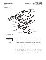
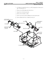
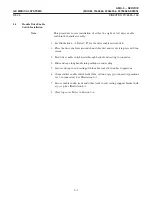
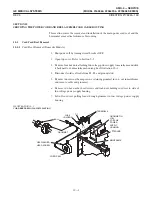
7. Slide end cap along handle away from end casting.
8. Remove end casting from handle assembly by removing two hex socket head
capscrews securing it to handle springs. Be careful not to damage sensor and
drive enable switch leads.
9. Remove two binding head capscrews securing sensor to standoff posts inside the
end casting.
10. Pull sensor leads through back ofend casting and remove sensor.
This procedure covers installation ofeither the right or left sensor in the hanĆ
dle assembly.
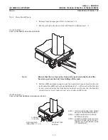
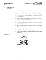
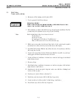
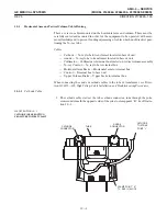
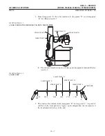
1. Position sensor on standoff posts inside end casting and secure with two binding
head capscrews. See Illustration 8-3.
2. Feed sensor leads through back end ofcasting to the connector.
3. Position handle assembly in end casting and secure handle springs to casting with
two hex socket head capscrews. Be careful not to damage sensor and drive enable
switch leads.
4. Slide end cap along handle and position on end casting.
5. Secure end cap on end casting with four hex socket button head capscrews.
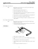
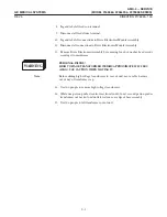
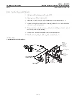
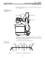
6. Connect sensor leads (red, white and black - positions 3, 4 & 5 in connector) to
connector). See Illustration 8-2.
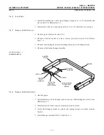
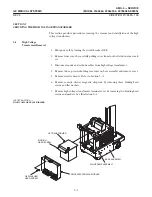
7. Fasten handle assembly to two support brackets with eight hex flange head
capscrews. See Illustration 8-1.
8. Connect connectors at each end ofhandle assembly.
9. Connect ground wire, located at left end of handle, to mainframe.
10. Attach wires to the handle assembly angle support bracket with ty-raps.
11. Close top cover. Refer to Section 5-6.
Summary of Contents for AMX 4+
Page 1: ...0 0 1 1 2 2...
Page 2: ......
Page 3: ...D D D D D D D D D D D D D D D D...
Page 4: ...D D D D D D D D...
Page 6: ...iv...
Page 8: ...vi...
Page 14: ...xii...
Page 18: ...xvi...
Page 32: ...1 14...
Page 48: ...3 14...
Page 84: ...5 10...
Page 106: ...7 12...
Page 112: ...8 6...
Page 116: ...9 4...
Page 131: ......
Page 132: ...3 2 2 1 0 3 5 0 2 0 4 0 2...


