background image


9-2

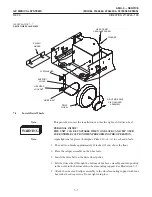
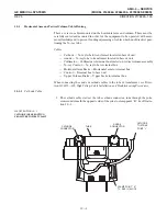
8. Tag and label all leads on terminal

9. Disconnect all leads from terminal.

10. Tag and label all connections to Drive Electronics Module Assembly.

11. Disconnect all connections to Drive Electronics Module Assembly.

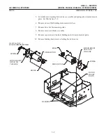
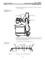
12. Remove Drive Electronics Assembly by removing four hex washer head screws

securing it to mainframe.

 !

     !  


#$"

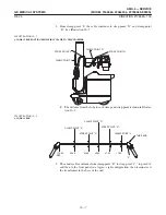
Before sliding high voltage transformer to rear of unit, move cable harness

out of way of transformer cap.

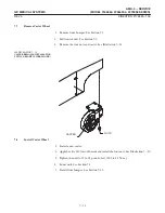
13. Use two people to remove high voltage transformer.

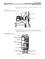
14. While one person pushes transformer from front of unit, second person guides

transformer out back of unit untilit rests on rear edge of base assembly.

15. Use two people to lift transformer out of unit.

Summary of Contents for AMX 4+

Page 1: ...0 0 1 1 2 2...

Page 2: ......

Page 3: ...D D D D D D D D D D D D D D D D...

Page 4: ...D D D D D D D D...

Page 5: ...t the possibility of any persons carelessly exposing themselves or others to radiation It is important that everyone having anything to do with x radiation be properly trained and fully ac quainted wi...

Page 6: ...iv...

Page 7: ...vic ing on the equipment All packages should be closely examined at time of delivery If damage is apparent have notation 3 1 4 written on copies of the freight or express bill 02 delivery is accepted...

Page 8: ...vi...

Page 9: ...3 Yoke Mounting Plate Assembly Removal 3 3 3 4 Yoke Mounting PlateAssembly Installation 3 5 3 5 Horizontal Arm Assembly Removal 3 6 3 6 Horizontal Arm Assembly Installation 3 8 3 7 Horizontal Arm Brak...

Page 10: ...4 7 Lower Brake Removal 4 21 4 8 Lower Bearings and Baseplate Removal 4 22 4 9 Lower Brake and Bearings Installation 4 22 4 10 Column Base Removal 4 23 4 11 Column Base Installation 4 24 4 12 Lower Pu...

Page 11: ...tallation Connection 6 9 6 15 Install Battery Compartment Cover 6 10 7 SERVICING THE BASE ASSEMBLY 7 1 7 1 Front Bumper 7 1 7 1 1 Remove Pads 7 1 7 1 2 Install Pads 7 2 7 1 3 Bumper Switch Removal 7 2...

Page 12: ...estic Models 10 1 10 1 2 Cord Reel Removal IEC Models 10 2 10 2 Cord Cord Reel Installation 10 3 10 2 1 Cord Reel Installation Domestic Models 10 3 10 2 2 Cord Reel Installation IEC Models 10 3 10 3 H...

Page 13: ...fied vertical arm latch switch to new style added latch wiring diagram in Section 9 3 Aug 14 1997 High Impact Inspection 4 Apr 12 1999 Added AMX 4 Model 2236420 Series 5 Nov 8 2000 Added AMX 4 Model 2...

Page 14: ...xii...

Page 15: ...60 8 A0659FA 2236420 8 2275938 8 A0659JG DOMESTIC TECH SWITCH 2169360 9 A0659FC 2236420 9 2275938 9 A0659JH DOMESTIC AEC TECH SWITCH 2169360 10 A0659FB 2236420 10 2275938 10 A0659JJ IEC EMC 2169360 A0...

Page 16: ...ight Lifting Tool 46 303491G1 D HHS Field Test Kit 46 177372G1 D Torque Wrench 2 36 pound inches 0 23 4 1 Newton meters 46 282782P1 D Torque Wrench Kit 46 268445G1 D H V Cable Spanner Wrench 507A935G1...

Page 17: ...5 4 7 4 9 4 11 4 13 4 15 4 17 4 19 4 21 4 23 4 2 4 4 4 6 4 8 4 10 4 12 4 14 4 16 4 18 4 20 4 22 4 24 Section 5 Servicing the Trim Covers Cassette Drawer Side Covers Top Cover 5 1 5 3 5 5 5 2 5 4 5 6 S...

Page 18: ...xvi...

Page 19: ...ing upward 3 Place the horizontal arm assembly in park position on top cover of unit 0 0 4 1 5 1 2 2 0 2 3 5 3 3 0 0 0 3 0 2 4 Shut off power by turning circuit breaker OFF 5 Remove two screws in bott...

Page 20: ...align ment is altered the plate will have to be re aligned in the field 1 Close collimator blades 2 Rotate X ray tube and collimator assembly so collimator crosshair window is facing upward 3 Place th...

Page 21: ...SCREWS PORT PLATE INTERFACE PLATE TUBE HOUSING TUBE HOUSING 10 32 X 0 50 INCH INTERFACE PLATE SCREWS 6 Remove collimator from interface plate 7 Carefully place collimator and cables on horizontal arm...

Page 22: ...r upside down and insert cone into the tube port interface plate Align mounting screw holes 4 Attach collimator assembly to tube port interface plate with three 10 24 0 75 inch hex socket head cap scr...

Page 23: ...Carefully remove the lamp by pulling it straight back and out of its receptacle Replace it with a new lamp Refer to renewal parts listing for correct lamp 4 Whenever a lamp is replaced the light fiel...

Page 24: ...eld areas Adjustment Method 1 1 Place loaded cassette 14 17 inches suggested on floor directly beneath colli mator 2 Adjust the collimator so that it is parallel to the cassette 3 Set SID to 40 inches...

Page 25: ...l of the horizontal differences as well as the total of the vertical differ ences must each be less than 1 8 of the SID D A B 1 8 SID A B 0 018 40 inches A B 0 72 inches D C D 1 8 SID C D 0 018 40 inc...

Page 26: ...Alternately tightening the two screws will help prevent the bracket from slipping out of place 19 Repeat steps 1 through 16 until the percentage of SID requirements are ob tained If the percentage of...

Page 27: ...k size of field See Illustra tion 1 7 6 Expose film Do not move film cassette D 60 kVp 2 mAs 7 Open collimator blades 8 Expose film a second time and develop the film D 60 kVp 2 mAs This exposure shou...

Page 28: ...not met proceed with the following steps Ideally the x ray field and the light field should coincide but this is rarely the case The best compromise is to move the light field so the x ray field is ce...

Page 29: ...or crosshair window posi tion should be checked and corrected if necessary 2 Place Light Field to X Ray Field Test Pattern 46 198466P1 directly under the collimator If the test pattern is not availabl...

Page 30: ...will easily snap out of the panel A short length of two wires will be attached to the switch Use care not to scratch the panel during this procedure See Illustration 1 2 4 Unsolder the two wires 5 Res...

Page 31: ...from the switch retaining plate Remove the plate 5 Lift off the switch button and button return spring 6 Pull the switch from the handle 7 Unsolder the two wires 8 Solder the two wires onto the new r...

Page 32: ...1 14...

Page 33: ...1 1 Remove collimator from x ray tube Refer to Section 1 1 steps 1 through 10 for removal instructions 2 Disconnect anode and cathode High Voltage cable connectors from x ray tube See Illustration 2 1...

Page 34: ...able bracket Replace cable clamp and secure in place using three socket head cap screws 4 Connect control cable leads to terminal block on tube cable bracket in accor dance with connection data record...

Page 35: ...1 Remove the collimator Refer to Section 1 2 Remove the X ray tube Refer to Section 2 EYE INJURY WEAR EYE PROTECTION WHEN REMOVING THE YOKE ASSEMBLY SOME PARTS ARE SPRING LOADED AND MAY CAUSE INJURY...

Page 36: ...thrust bearing on horizontal arm shaft See Illustration 3 1 3 Place yoke mounting plate with tube supports on horizontal arm shaft 4 Slide thrust washer disk and three spring washers onto horizontal a...

Page 37: ...mounting plate shaft 6 Slide shaft disk and mounting plate from right tube support 7 Remove two small bearings and their shaft from right tube support 8 Remove four screws holding shaft and disk to m...

Page 38: ...rt 14 Remove thrust washer and dowel pin from shaft 15 Remove four screws holding shaft and disk to mounting plate 16 Remove shaft and disk from mounting plate 17 Remove eight hex socket flat head cap...

Page 39: ...over to mounting plate shaft with four capscrews 7 Replace decal on cover Left Mounting Plate 8 See Illustration 3 3 Place mounting plate shaft and disk on mounting plate 9 Secure shaft and disc to mo...

Page 40: ...allows the arm to ascend rapidly possibly causing damage to the unit and personal injury 2 Support the x ray tube and collimator using chain hoist or other suitable equip ment ILLUSTRATION 3 4 REMOVAL...

Page 41: ...REV 5 DIRECTION 2173225 100 3 7 ILLUSTRATION 3 5 CARRIAGE 1 4 20 X 3 4 HEX SOCKET HEAD SCREWS 3 AND WASHERS 3 HORIZONTAL ARM COLUMN 1 4 20 X 3 4 LG HEX SOCKET HEAD SCREWS 4 AND WASHERS 4...

Page 42: ...ction data recorded and tagged on leads 6 Position back cover on terminal box and secure with two screws Equipment Damage The horizontal arm must be secured before installing components on the arm Do...

Page 43: ...Remove the two stop block capscrews securing the brake and cable assembly to the end of the outer tube See Illustration 3 6 ILLUSTRATION 3 6 STOP BLOCK CAPSCREWS 10 32 X 1 2 HEX SOCKET FLATHEAD LATCH...

Page 44: ...tube 12 Remove the two brake capscrews holding the brake cable assembly to the rear of the center tube 13 Remove two or three screws depends on unit you have holding the connector bracket and ground w...

Page 45: ...7 Secure the connector bracket and ground wire to the center tube with two or three screws depends on unit you have 8 Replace mounting plate capscrew holding brake and cable assembly to the center tub...

Page 46: ...5 8 INCH SCREW 10 32X1 INCH SCREW 10 32X5 8 INCH SCREW MOUNTING BLOCK PULLEY CABLE PULLEY BAR WASHER PULLEY BEARING MASTER LINK MOUNTING BLOCK CABLE BAR BRAKE CHAIN BRAKE CABLE MASTER LINK BRAKE WIRIN...

Page 47: ...able and chain move freely 6 Loctite the anchor nut 7 Install horizontal arm brake and cable assembly Refer to Section 3 8 1 Remove horizontal arm brake and cable assembly Refer to Section 3 7 2 Disco...

Page 48: ...3 14...

Page 49: ...s See Illustration 4 1 3 Remove Heyco bushing and cable through bottom of terminal box 4 Clear all cables and wires from the column area 5 Remove vertical column cap by removing two hex socket button...

Page 50: ...cover away from column support base 12 Break loose the column support bearing from the column support base by jacking the column out using three 1 4 20 screws thru the base plate and against the sup...

Page 51: ...Torque to 100 pound inches 11 3 N m 6 Connect brake connectors to brake See Illustration 4 2 7 Secure cover on column support base with two screws 8 Replace trim cover at base of column Refer to Sect...

Page 52: ...re directed 1 Set the main power circuit breaker to OFF 2 Position horizontal arm and tube at least 90 degrees out of park so that it can be positioned at lowest possible position 3 Raise horizontal a...

Page 53: ...2 Remove holding nut on bottom of stud end of main cable 3 Remove cable stud from carriage cable mounting strut 4 Move horizontal arm to bottom of column D This raises the counterweight to the top of...

Page 54: ...e stud 16 Install cable stud through carriage horizontal bar and install holding nut 17 Set cable to tension in accordance with Section 4 3 4 Tighten cable jam nut Do not allow cables to twist while s...

Page 55: ...ile setting tension Reassemble Unit 1 Replace carriage access plate and four binding head screws 2 Install column cap 3 Move horizontal arm through full range of motion ensuring that it moves smoothly...

Page 56: ...or in the event the procedure in Section 4 3 cannot be successfully performed 1 Remove vertical column from unit Refer to Section 4 1 Vertical Column re moval is necessary in order to replace a follo...

Page 57: ...ve carriage toward top of column until ball end of follower cable is exposed Move ball end of cable to bottom of column 9 Remove follower cable from lower pulley and leave inside bottom of column 10 R...

Page 58: ...main safety cable studs into carriage cable mounting strut holes 9 Replace holding nuts on bottom of stud ends of main and safety cables Do not tighten at this time 10 Make certain all the cables are...

Page 59: ...vertical col umn and lift off cover 5 Disconnect upper brake cable leads from terminal block It is important to tag and record terminal points otherwise there is a possibility of blowing internal diod...

Page 60: ...ey and brake assembly by first lifting it from its pulley groove moving it to the side of the pulley and then pulling it free The ball ends of these cables still remain attached to counterweight 13 Re...

Page 61: ...ud ends of main and safety cables 3 Insert each cable into pulley and brake assembly along the side of the pulley then lift it into its assigned pulley groove D The ball ends of these cables are attac...

Page 62: ...tical column 1 Remove horizontal arm Refer to Section 3 5 D It is not necessary to remove yoke from arm 2 Disconnect upper brake Refer to Section 4 4 1 3 Disconnect main and safety cables from carriag...

Page 63: ...through column and enters pulley and brake assembly Bushing extends into pulley and brake casting 5 Apply Loctite and replace capscrews securing pulley and brake assembly to top of column Torque to 50...

Page 64: ...ty and follower cables Refer to Section 4 3 3 Remove upper pulley and brake assembly Refer to Section 4 4 4 Slide counterweight from vertical column 5 Remove top cable retainer clip from counterweight...

Page 65: ...nserting ball ends of cables into retaining notch in top of counterweight See Illustration 4 9 2 Replace cable retainer clip in top of counterweight assembly and secure with two slotted hex washer cap...

Page 66: ...oving forces are unequal eight oz 0 23 kg counterweights part number 46 279784P1 should be added or removed approximately four are in stalled at the factory a Move the tube arm to its lowest possible...

Page 67: ...k that horizontal arm mounting plate is at top of carriage 2 Install pulley and brake assembly Refer to Section 4 6 3 Place follower cable end into carriage strut and secure in place by tightening its...

Page 68: ...s to carriage mounting flanges with hex head shoulder bolts See Illustration 4 11 Apply Loctite and torque to 40 60 pound inches 4 5 to 6 7 N m 3 Install side facing bearings at mounting locations on...

Page 69: ...ase shaft See Illustration 4 12 ILLUSTRATION 4 12 COLUMN BEARING PLATE COLUMN BASE SHAFT LOWER COLUMN BEARING UPPER COLUMN BEARING 3 Pull lower column bearing from column base shaft 4 Remove screws an...

Page 70: ...op disk in column bearing plate if it has come out 1 Install upper column bearing in column bearing plate See Illustration 4 12 2 Place column bearing plate on column base shaft Ensure that column bea...

Page 71: ...ble Refer to Section 4 3 5 3 Remove lower brake and bearings Refer to Sections 4 7 and 4 8 4 Remove hex head bolt and flat washers securing column base assembly to vertical column See Illustration 4 1...

Page 72: ...up with column base and column 3 Apply Loctite to the hex head bolts Secure column base assembly to vertical col umn with bolts and flat washers Torque bolts to 30 35 pound feet 41 to 47 N m 4 Instal...

Page 73: ...lley shaft 4 Pull out shaft and remove pulley 5 Remove bearings from column base casting 1 Insert bearings in bearing seats in column base casting See Illustration 4 14 2 Push pulley shaft through lef...

Page 74: ...ckwashers and flat washers securing the column support to the base assembly 4 Remove column support from base assembly 1 Place column support in base assembly Orient opening in side of column support...

Page 75: ...ette drawer hinge to base assembly 3 Pull cassette drawer to open position It is retained by magnetic catch Lift drawer up and out of base assembly ILLUSTRATION 5 1 HANDLE CASSETTE DRAWER SCREWS REAR...

Page 76: ...base assembly 4 Disconnect hand switch on right side trim cover 5 Remove two 4 40 x 3 8 inch binding head screws and one 6 32 x 1 2 inch black oxide binding head screw holding each cover to base and...

Page 77: ...32 x 1 2 inch black oxide binding head screw 4 Connect handswitch on right side trim cover 5 Install rear cover with two screws 6 Install front cover on unit by pressing ball studs on corners of cove...

Page 78: ...ackets 9 Remove the top cover 1 Move horizontal arm to top of column 2 Turn power off by turning circuit breaker OFF 3 Extend right and left hinges from mainframe to vertical position See Illustration...

Page 79: ...terminal strip you may remove four hex nuts at taching low voltage power supply to mainframe and slide power supply back ward out of mainframe housing See Illustration 5 4 ILLUSTRATION 5 4 BINDING HE...

Page 80: ...NAL STRIP WHITE 5 Remove latch assembly from mainframe by removing four hex socket head capscrews 6 Remove latch block from spacer by removing four hex socket head capscrews 7 Push spring pin out of l...

Page 81: ...o retain latch in position 8 Install latch block on spacer and fasten with four hex socket head capscrews 9 Install latch assembly on mainframe and fasten with four hex socket head capscrews 10 Connec...

Page 82: ...amp then remove the clamp and star washer To install the hand switch cable perform the above steps in reverse order Be sure to align the cable to the cover as indicated in Illustration 5 6 ILLUSTRATIO...

Page 83: ...5 9 1 Plug end of coil cord into X Ray Hand Switch 2 Place X Ray Hand Switch on support bracket ILLUSTRATION 5 7...

Page 84: ...5 10...

Page 85: ...Battery numbers may or may not be marked on batteries Mark batteries with numbers if desired D Disconnect cables only in the order instructed and only when instructed D Don t remove paper backing fro...

Page 86: ...ng cables from ground stud See Illustration 6 1 Tape each cable separately Keep ALL cables separate 6 Remove battery lead cable marked 4 from terminal on Circuit Breaker in AMX1 A3 Module Be certain b...

Page 87: ...r cable terminal See Illustration 6 3 2 Disconnect Cable 5 from Battery 9 and slide boot over cable terminal 3 Remove Battery 9 Insulator 8 and Insulator 1 in front of Batteries 7 and 8 4 Disconnect s...

Page 88: ...S 1 3 2 4 5 6 AND 7 8 DON T REMOVE PAPER BACKING FROM BATTERY SEPARATOR PADS ORIENT PADS WITH PAPER BACKING FACING UP CABLE 6 CABLE 8 CABLE 7 SENSE LEAD CABLE 7 2 5 CABLE 7 SENSE LEAD CABLE 6 SENSE LE...

Page 89: ...and slide boot over cable terminal Disconnect other end of Cable 4 from Battery 1 and slide boot over cable terminal 7 Disconnect Cable 8 from Battery 4 and slide boot over cable terminal 8 Disconnect...

Page 90: ...Ensure that new battery voltage is no more than 0 4 volts higher than average bat tery voltage when replacing individual batteries For severely discharged sets 112 Volts or less recharge the set for...

Page 91: ...to Battery 2 and connect other end to Battery 1 Slide a boot over each terminal 9 Connect end of Cable 8 without sense lead to Battery 4 and slide a boot over this terminal Orient cable so that the t...

Page 92: ...6 Sense Lead from Battery 3 to J3 RHS 5 Connect Cable 4 Sense Lead from Battery 1 to J1 RHS 6 Connect Cable 1 Sense Lead from Battery 6 LHS left hand side 7 Connect Cable 8 Sense Lead from Battery 5...

Page 93: ...ead to prevent it from shorting after it is connected to Battery 9 6 Connect other end of Cable 2 to Battery 9 and slide a boot over cable terminal Route Cable 2 through grommet in hole in top of batt...

Page 94: ...L FLOOR BOLTS TORQUED TO 75 IN LBS 8 4 N m Distribution of weight is necessary to install the battery compartment cover 2 Place the remaining Insulator 1 in the compartment opening with cup shaped bum...

Page 95: ...bolts from each pad and remove the corner pads See Illustration 7 1 2 Remove the 10 32 x 1 25 inch bolts and flat washers securing the front bumper and remove the middle piece of the front bumper ILL...

Page 96: ...ension on switch actuator See Illustra tion 7 2 3 Remove two binding head screws holding switch on end of bumper track 4 Remove switch from bumper assembly ILLUSTRATION 7 2 Bumper Switch Installation...

Page 97: ...gs 6 Remove bearing from mounting slot in bumper by removing hex head screw spacer and shaft Bumper Bearings Installation This procedure covers the removal of any one or more of the eight bearings com...

Page 98: ...t of the jack See Illustration 7 4 ILLUSTRATION 7 4 Raise Rear Wheels 1 Rotate front wheel caster toward rear otherwise unit will be unstable when rear of unit is raised 2 Block the front wheel and li...

Page 99: ...in Illustration 7 6 Be sure that the block s is are centered under the front battery box wall and be sure that the block s extend s out at least 2 inches 5 cm on each side of AMX unit ILLUSTRATION 7...

Page 100: ...motor and brake assembly Refer to Section 7 5 4 Lift the rear of the unit See Section 7 2 5 Loosen the four locknuts and flat washers holding the wheel support angle to the base assembly See Illustra...

Page 101: ...e Lubriplate Fiske 630 A A to each end of axle 1 The unit is on blocks approximately 10 inches 25 cm above the floor 2 Place the caliper assembly on the wheel axle 3 Install the drive belt on the driv...

Page 102: ...ches 4 5 to 6 7 N m 9 Install splash guard and secure with two lock nuts 10 Install the motor and brake assembly Refer to Section 6 10 11 Lower the unit to the floor This procedure covers the removal...

Page 103: ...base 7 Remove drive belt from motor pulley 8 Remove motor and brake assembly 9 Remove capscrews and washers holding motor to motor mount plate 10 Remove binding head screws attaching brake to motor I...

Page 104: ...ration 7 9 4 Install motor and brake assembly in the base assembly 5 Attach motor mount to base with nut and motor mount bolt and tighten finger tight 6 Place drive belt in position on motor pulley 7...

Page 105: ...uts and caster See Illustration 7 10 ILLUSTRATION 7 10 NUTS CASTER 1 Install a new caster 2 Apply Loctite 242 to stud threads and install the four nuts See Illustration 7 10 3 Tighten the nuts to 15 t...

Page 106: ...7 12...

Page 107: ...1 Open top cover and place in position to easily access the handle assembly Refer to Section 5 5 2 Disconnect connector at each end of handle assembly See Illustration 8 1 3 Cut the two ty raps holdin...

Page 108: ...r from connector See Illustration 8 2 ILLUSTRATION 8 2 RED WHT BLK 1 FROM DRIVE ENABLE SWITCH 2 FROM DRIVE ENABLE SWITCH 3 FROM SENSOR 4 FROM SENSOR 5 FROM SENSOR 6 Detach end cap from end casting by...

Page 109: ...sensor leads through back end of casting to the connector 3 Position handle assembly in end casting and secure handle springs to casting with two hex socket head capscrews Be careful not to damage se...

Page 110: ...the other wires blue yellow or gray positions 1 2 in connector See Illustration 8 2 4 Disconnect drive enable switch leads from connector 5 Remove end cap from end casting by removing four hex socket...

Page 111: ...eed drive enable switch leads through back of end casting to connector 4 Slide end cap along handle into position on end casting 5 Secure end cap to end casting with four hex socket button head capscr...

Page 112: ...8 6...

Page 113: ...sock ets 3 Disconnect anode and cathode cables from high voltage transformer 4 Remove two cap screws holding rear cover on base assembly and remove cover 5 Remove cassette drawer Refer to Section 5 1...

Page 114: ...nics Assembly by removing four hex washer head screws securing it to mainframe Before sliding high voltage transformer to rear of unit move cable harness out of way of transformer cap 13 Use two peopl...

Page 115: ...e Electronics Module Assembly and secure it to mainframe with four hex washer head screws 6 Connect all connections to Drive Electronics Module Assembly in accordance with tagged and labeled instructi...

Page 116: ...9 4...

Page 117: ...low voltage power supply to mainframe and slide it backward out of mainframe housing See Illustration 10 1 4 Disconnect cord reel leads from F1 F2 and ground stud 5 Remove two internal hex cap screws...

Page 118: ...stration 10 2 4 Remove two internal hex cap screws retaining grommet in cut out in mainframe and remove cable and grommet 5 Remove two hex washer head screws and lock nuts holding cord reel to side of...

Page 119: ...de low voltage power supply into mainframe housing and fasten with four hex nuts 7 Close top cover Refer to Section 5 6 Cord Reel Installation IEC Models 1 Shut power off by turning circuit breaker OF...

Page 120: ...ocated on vertical column assembly X ray Control X ray tube to terminal box Horizontal Arm Brake Horizontal arm to terminal box Control Terminal box to base unit Upper Column Brake Upper brake to term...

Page 121: ...nues from clamp point H and strap point G to clamp point E to the front panel in a figure eight configuration and then terminates at the transformer in the base of the unit D The distances are referen...

Page 122: ...cable starts at the tube anode connector runs through the yoke crosses underneath to the opposite side of the yoke to clamp point D See Illus tration 10 6 ILLUSTRATION 10 6 CATHODE CONNECTOR ANODE TO...

Page 123: ...tance from the tube to each clamp and strap point is shown in Illustra tion 10 8 ILLUSTRATION 10 8 CLAMP POINT L CLAMP POINT A CLAMP POINT D TUBE END 0 17 00 49 00 90 00 STRAP POINT C 83 00 STRAP POIN...

Page 124: ...o the cathode cable There is a large loop of cable before reaching strap point J as shown in Illustration 10 9 ILLUSTRATION 10 9 ANODE CABLE CATHODE TUBE STRAP POINT J COLLIMATOR CABLE ANODE CATHODE C...

Page 125: ...he collimator cable goes from strap point C directly into the vertical column assembly terminal box where it is connected to terminal strip AMX3 A1 TS1 See Illustration 10 12 and Table 10 1 ILLUSTRATI...

Page 126: ...UBE 6 8 WHT BRN WHT AMX3 A4 COLLIMATOR 7 9 WHT RED YEL AMX3 A4 COLLIMATOR 8 10 WHT BLK RED AMX3 BRK2 COLUMN LOCK 9 RED AMX3 A2 J1 TUBE ARM LOCK 10 11 VIO BLK AMX3 BRK2 COLUMN LOCK RTN 11 BLK AMX3 A2 J...

Page 127: ...before reaching clamp point L The cables are ty rapped on each side of clamp point L as shown in Illustration 10 13 ILLUSTRATION 10 13 COLLIMATOR CABLE ANODE CLAMP POINT L CATHODE CATHODE STATOR CABL...

Page 128: ...14 5 There is a large loop after strap point G before the cable enters the bottom of the vertical column assembly terminal box and is connected to the terminal strip AMX A1 TS1 See Illustration 10 12...

Page 129: ...embly terminal box and is connected to the terminal strip AMX3 A1 TS1 See Illustration 10 12 and Table 10 1 Control Cable The control cable exits the bottom of the terminal box on the rear of the vert...

Page 130: ...and is routed to a channel on the rear of the column See Illustration 10 18 ILLUSTRATION 10 18 2 The brake cable enters the channel at the top of the vertical column assembly and continues down into t...

Page 131: ......

Page 132: ...3 2 2 1 0 3 5 0 2 0 4 0 2...

Reviews: