


CHAPTER 5: SETTINGS
FLEXLOGIC
L60 LINE PHASE COMPARISON SYSTEM – INSTRUCTION MANUAL
5-133
5
5.5 FlexLogic
5.5.1 FlexLogic operands
For flexibility, the arrangement of internal digital logic combines fixed and user-programmed parameters. Logic upon
which individual features are designed is fixed, and all other logic, from contact input signals through elements or
combinations of elements to contact outputs, is variable. The user has complete control of all variable logic through
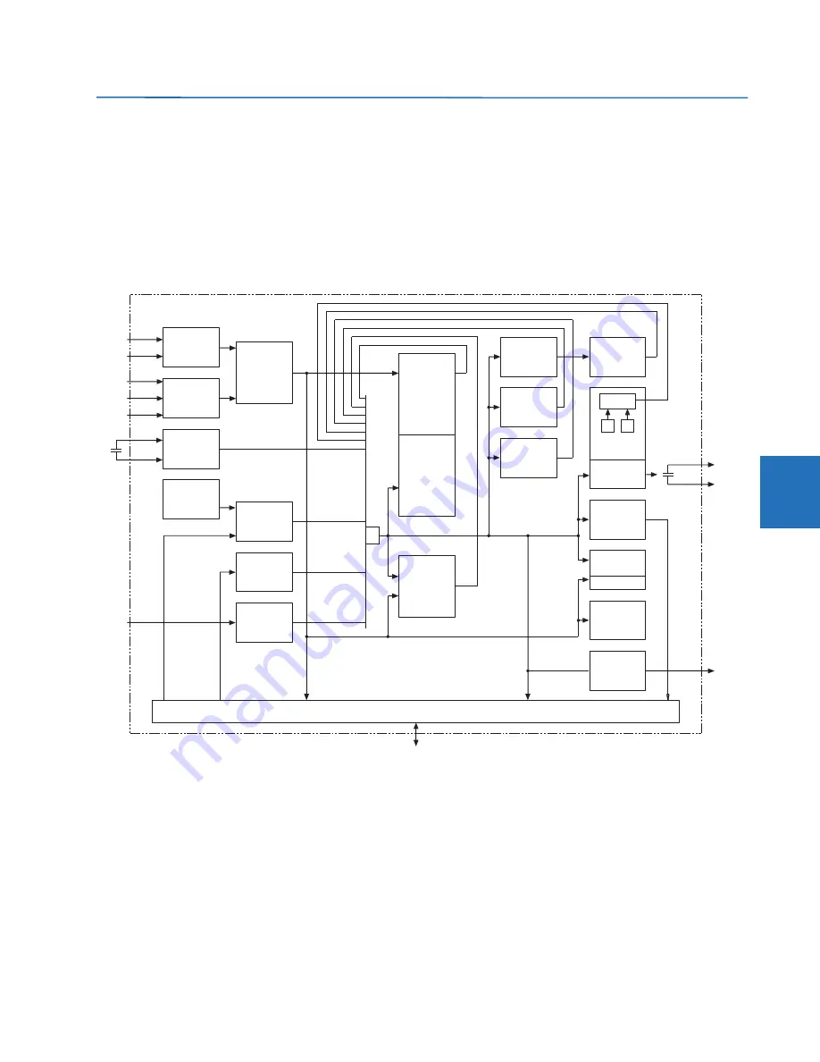
FlexLogic. In general, the system receives analog and digital inputs that it uses to produce analog and digital outputs. The
figure shows major subsystems of a generic UR-series relay involved in this process.
Figure 5-63: UR architecture overview
The states of all digital signals used in the L60 are represented by flags (or FlexLogic operands, which are described later in
this section). A digital “1” is represented by a set flag. Any external contact change-of-state can be used to block an
element from operating, as an input to a control feature in a FlexLogic equation, or to operate a contact output. The state
of the contact input can be displayed locally or viewed remotely via the communications facilities provided. If a simple
scheme where a contact input is used to block an element is wanted, this selection is made when programming the
element. This capability also applies to the other features that set flags: elements, virtual inputs, remote inputs, schemes,
and human operators.
If more complex logic than shown in the figure is required, it is implemented via FlexLogic. For example, to have the closed
state of contact input H7a and the operated state of the phase undervoltage element block the operation of the phase
time overcurrent element, the two control input states are programmed in a FlexLogic equation. This equation ANDs the
two control inputs to produce a virtual output that is then selected when programming the phase time overcurrent to be
used as a blocking input. Virtual outputs can only be created by FlexLogic equations.
EnerVista UR Setup and LAN communications
DCmA
or
RTD
inputs
VTs
CTs
DSP
(A/D)
827022A7.cdr
Analog
input
(A/D)
Calculate
parameters
Contact
inputs
Keypad
Virtual
inputs
Remote
inputs
(GOOSE)
OR
fiber
G.703
RS422
Direct
inputs
Control
and
monitoring
features
Block
operation
(each
element)
Measuring
and
decision
elements
FlexLogic™
equations
Flags
FlexLogic™
counters
Virtual
outputs
Digital
elements
V
I
Form-A and
SCR only
Contact
outputs
Display
and LEDs
Remote
outputs
Display
Analog
output (D/A)
(dcmA)
Direct
outputs
Fiber
G.703
RS422
(Status)
(Status)
(Actual values)
(FlexLogic operands)


