


8.
Slide
new
compression
fitting
nuts
and
then
ferrules
over
the
ends
of
the
replacement
heaters.
9.
Insert
the
ends
of
the
heating
elements
into
the
male
fittings
in
the
heater
plate.
Ensure
that
the
ends
of
the
heaters
do
not
protrude
too
far,
which
would
potentially
interfere
with
the
cover
of
the
heater
box.
Insert
a
wrench
or
other
flat
tool
through
the
loop
end
of
the
heating
element
to
prevent
it
from
twisting.
Tighten
the
compression
fitting
nut
firmly
using
an
11/16”
flare
nut
wrench.
10.
Reinstall
RTD’s
by
inserting
into
Swagelok
fitting
and
tightening
nut
finger
tight
then
1/4
turn.
The
long
RTD
is
installed
in
the
right
fitting,
on
right
leg
of
center
heater
element.
The
short
RTD
is
installed
in
the
center
fitting,
on
left
leg
of
center
heater
element.
11.
On
the
long
probe,
compress
and
slide
a
spring
to
the
center
of
the
probe.
On
both
the
long
and
short
probe,
compress
and
slide
the
spring
over
the
end
of
the
RTD’s
until
approximately
3/8”
of
the
RTD
probe
extends
beyond
the
spring.
12.
Slide
a
new
heater
block
gasket
over
the
stud
bolts
on
the
heater
block.
13.
Insert
the
heater
assembly
into
the
jacket
opening
and
over
the
stud
bolts.
Ensure
the
white
Teflon
isolation
bushings
are
reused
and
are
flush.
14.
Place
isolation
washers
(up
against
heater
plate),
large
stainless
washers,
lock
washers
and
nuts
onto
the
stud
bolts,
and
tighten
using
a
circular
‐
type
pattern
to
slowly
and
evenly
compress
the
gasket
to
make
a
water
‐
tight
seal.
Using
a
torque
wrench,
tighten
each
nut
to
a
final
torque
of
120
inch
‐
lb.
15.
Making
sure
to
counter
‐
torque
on
the
inner
nut
with
3/8”
wrench
and
a
torque
wrench
on
the
outer
nut,
reconnect
all
the
heater
wires
and
tighten
to
a
final
torque
of
35
inch
‐
lb.
16.
Reconnect
the
white
RTD
Connector.
17.
Reinstall
the
Heater
Plate
Enclosure,
Gasket
(notch
side
down),
Heater
Assembly
Cover,
and
Back
Lower
Panel.
18.
Inspect
heater
block
for
leaks
upon
first
use.
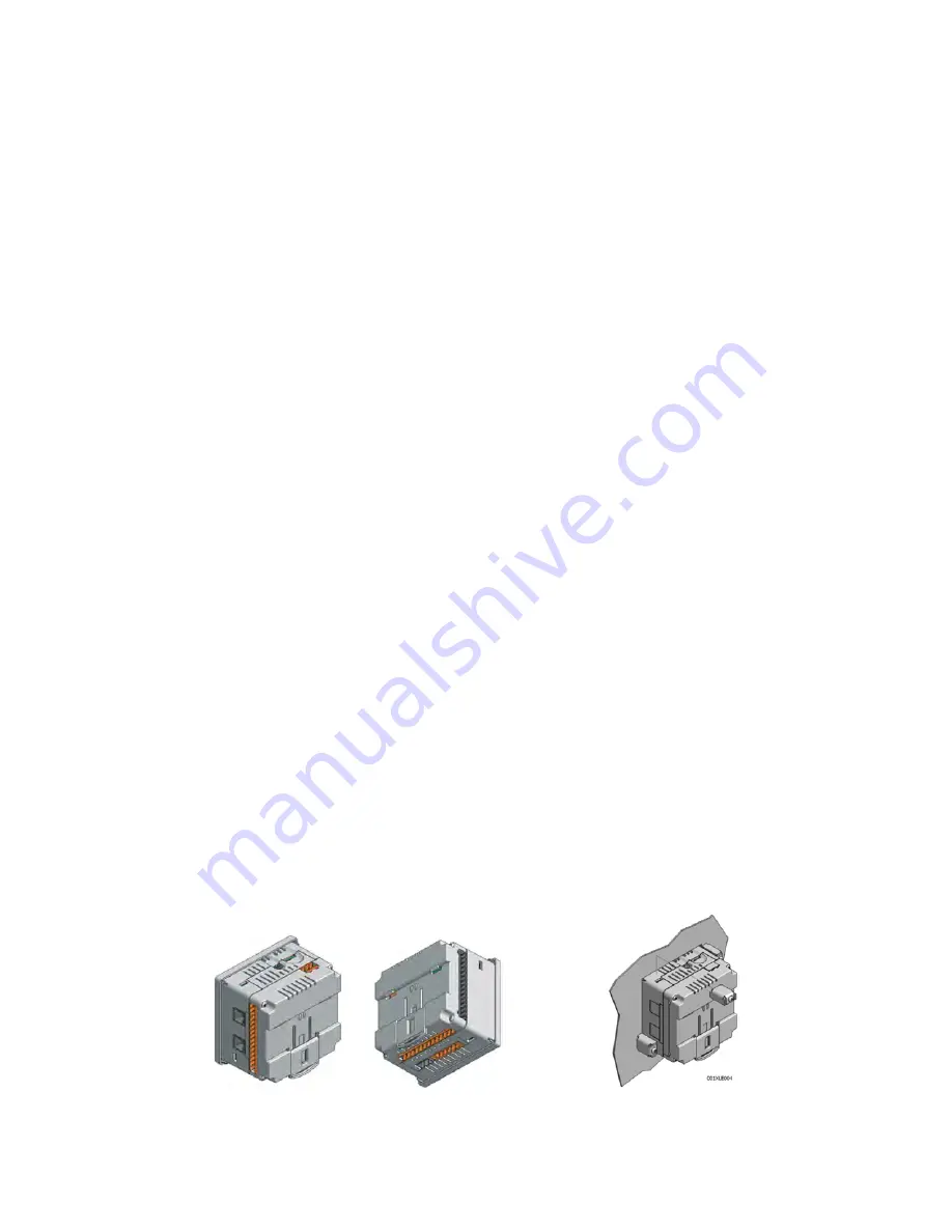
4.3.11
Replacing
the
PLC
NOTE:
Please
reference
the
Horner
XLT103
manual
found
on
the
CD
for
further
information.
CAUTION:
Be
aware
that
the
glass
fiber
optic
cable
for
the
door
switch
is
located
near
the
back
of
the
PLC.
Use
caution
when
removing
the
PLC
so
that
the
fiber
optic
cable
does
not
get
damaged.
90
Summary of Contents for P2131
Page 121: ... THIS PAGE INTENTIONALLY LEFT BLANK 115 ...
Page 130: ...SECTION A APPENDIX 124 ...
Page 131: ...A 1 Swagelok Fitting Installation Instructions 125 ...
Page 135: ...A 2 PLC Data Sheet 129 ...
Page 141: ...A 3 VERIFY Product Information 135 ...
Page 147: ...A 4 WRS Pump Information 141 ...
Page 158: ...A 5 Vacuum Leak Test Troubleshooting Guide 152 ...