


Disassembly and Assembly
Rev. A
3-3
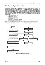
3.2 Disassembly and Assembly
This section describes how to disassemble the printer. Unless otherwise specified, no
assembly procedures are included, since it is usually performed by reversing the
disassembly procedures. Points to note at disassembling and assembling are described
under the heading
WORK POINTS
. Adjustments required after assembling are described
under the heading
REQUIRED ADJUSTMENTS
.
Be sure to follow the instructions and perform
any necessary adjustments. The procedure for disassembling the main component is
shown below:
1) Printhead replacement
2) Rear cover removal
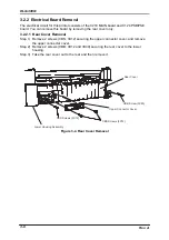
3) Electrical board removal
4) Control panel removal
5) Upper housing assembly removal
6) Printer mechanism disassembly
Refer to the exploded diagrams in Appendix for detailed part engagement and location.
Note) Perform “Control program reload” when C210 MAIN and sub boards are replaced.
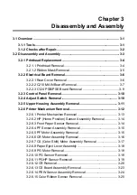
E l e c t r i c a l C i r c u i t B o a r d
R e m o v a l
A d j u s t S w i t c h R e m o v a l
P r i n t e r M e c h a n i s m D i s a s s e m b l y
L o w e r H o u s i n g A s s e m b l y
R e m o v a l
R e a r C o v e r R e m o v a l
C o n t r o l P a n e l R e m o v a l
P r i n t h e a d R e m o v a l
M a s k R i b b o n R e m o v a l
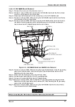
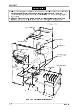
C 2 1 0 M A I N B o a r d
R e m o v a l
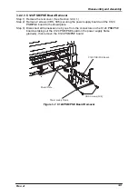
C 1 2 4 P S B / P S E B o a r d
R e m o v a l
R e l o a d i n g t h e C o n t r o l
P r o g r a m
U p p e r H o u s i n g A s s e m b l y
R e m o v a l
S T A R T
Figure 3-1. Disassembly Flowchart
Summary of Contents for DLQ-3000 Minerva+
Page 1: ...EPSON 24 PIN DOT MATRIX PRINTER EPSON DLQ 3000 SERVICE MANUAL SEIKO EPSON CORPORATION 4008259 ...
Page 5: ...v REVISION SHEET Revision Issued Data Contents Rev A August 21 1997 First Release ...
Page 61: ...2 3 12 Other Sensor Circuits 2 31 ...
Page 160: ...Chapter 6 Maintenance 6 1 Maintenance 6 1 6 1 1 Lubrication and Adhesion 6 1 ...
Page 171: ...DLQ 3000 Rev A A 6 ...
Page 172: ...Appendix Rev A A 7 A 2 Circuit Diagrams Figure A 2 C210 MAIN Board Circuit Diagram 1 2 ...
Page 173: ...DLQ 3000 Rev A A 8 ...
Page 174: ...Appendix Rev A A 9 Figure A 3 C210 MAIN Board Circuit Diagram 2 2 ...
Page 175: ...DLQ 3000 Rev A A 10 ...
Page 177: ...DLQ 3000 Rev A A 12 Figure A 5 C124 PSB Board Circuit Diagram ...
Page 180: ...Appendix Rev A A 15 Figure A 8 C210 MAIN Board Component Layout 2 2 ...
Page 181: ...DLQ 3000 Rev A A 16 Figure A 9 C124 PSB Board Component Layout ...
Page 182: ...Appendix Rev A A 17 Figure A 10 C124 PSE Board Component Layout ...
Page 189: ...EPSON SEIKO EPSON CORPORATION ...