


Adjustment
Rev. A
4-7
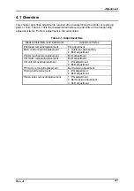
PG adjustment value verification
Step 1) Install the ribbon mask and the ink ribbon to the printer and the CR, respectively.
(Make sure that the printer power is off and the printer power cable is unplugged
from the AC power socket.)
Step 2) Switch the release lever setting to the continuous paper mode and set the paper
which meets the specification to the tractor.
Step 3) Turn the printer On.
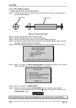
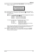
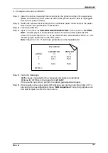
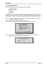
Step 4) Input “4” to select “4. PLATNEN GAP VERIFICATION” from the menu “PLATEN
GAP”, and the paper is automatically loaded. Then the printer prints the PG
amount for each step (from 1 to 9), as shown below, and indicates “Data X” and
“GTHK” (paper thickness) on the LCD panel.
Note: Values for
∗
, C, P and X are parameters in the hexadecimal.
PG CHECK
COMPUTER
PRINTER
ALPHA
∗
∗
-1
C(-1)
P(-1)
1
C(1)
P(1)
9
GTHK =
C(9)
P(9)
Step 5) Verify the followings:
PG values indicated for the computer and printer are identical.
Value for GTHK is in the range from 23 to 87.
If the result is not correct, perform the platen gap adjustment again.
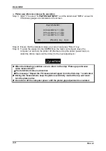
Step 6) If the results in the output and LCD indication are normal, turn the printer off. To
proceed to the next adjustment menu “Bi-D Adjustment”, stop the program once
and start it again to enter the main menu.
Summary of Contents for DLQ-3000 Minerva+
Page 1: ...EPSON 24 PIN DOT MATRIX PRINTER EPSON DLQ 3000 SERVICE MANUAL SEIKO EPSON CORPORATION 4008259 ...
Page 5: ...v REVISION SHEET Revision Issued Data Contents Rev A August 21 1997 First Release ...
Page 61: ...2 3 12 Other Sensor Circuits 2 31 ...
Page 160: ...Chapter 6 Maintenance 6 1 Maintenance 6 1 6 1 1 Lubrication and Adhesion 6 1 ...
Page 171: ...DLQ 3000 Rev A A 6 ...
Page 172: ...Appendix Rev A A 7 A 2 Circuit Diagrams Figure A 2 C210 MAIN Board Circuit Diagram 1 2 ...
Page 173: ...DLQ 3000 Rev A A 8 ...
Page 174: ...Appendix Rev A A 9 Figure A 3 C210 MAIN Board Circuit Diagram 2 2 ...
Page 175: ...DLQ 3000 Rev A A 10 ...
Page 177: ...DLQ 3000 Rev A A 12 Figure A 5 C124 PSB Board Circuit Diagram ...
Page 180: ...Appendix Rev A A 15 Figure A 8 C210 MAIN Board Component Layout 2 2 ...
Page 181: ...DLQ 3000 Rev A A 16 Figure A 9 C124 PSB Board Component Layout ...
Page 182: ...Appendix Rev A A 17 Figure A 10 C124 PSE Board Component Layout ...
Page 189: ...EPSON SEIKO EPSON CORPORATION ...