


Operating Principles
Rev. A
2-23
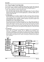
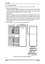
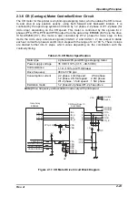
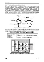
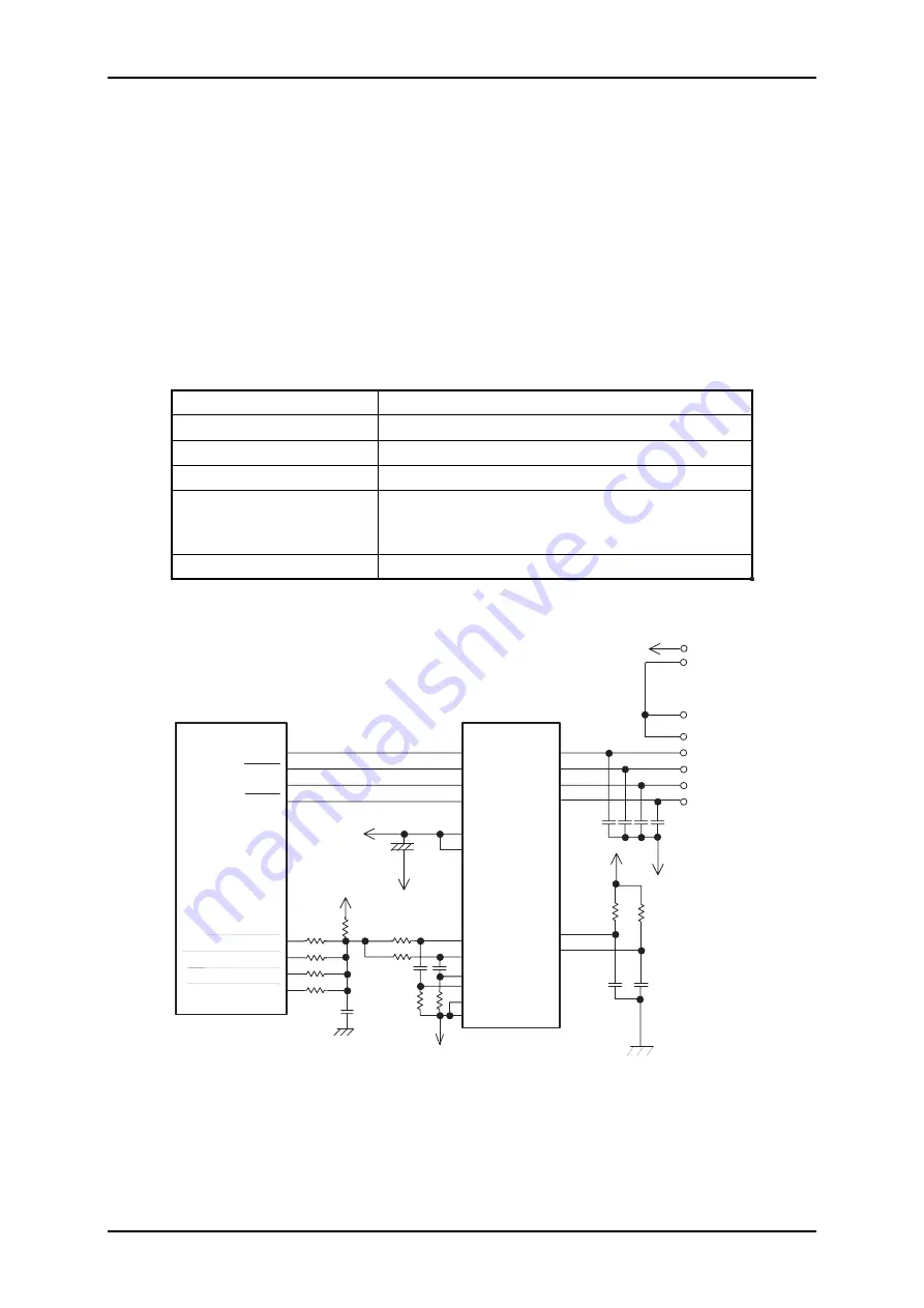
2.3.6 CR (Carriage) Motor Controller/Driver Circuit
The CR motor for this printer is a hybrid-type stepping motor, which enables the CR to move
to and stop at any position exactly, using both forward and backward rotation. It is
controlled by the open-loop system and driven by 1-2 phase, 2-2 phase or W1-2 phase (for
micro step), depending on the CR speed. This motor is controlled by the signals for 4
phases (PFA, /PFA, PFB and /PFB) output from the gate array E05B46 (IC25) via the drive
IC SLA7026M (IC7). The motor is also controlled by W1-2 phase for micro step. In this
mode, the micro step current set signals (/CASA1, 2 and CASA 1, 2) are output to divide
each set current for phase A and B into 4 steps with the range of 0 to 100 %. These 4 steps
are divided further into 8 steps, which varies depending on the combination with the
continuity timing.
Table 2-13. CR Motor Specification
Motor type
4 phases/200-pole/HB-type stepping motor
Power supply voltage
35 VDC
±
10% (31.5
−
38.5 VDC)
Coil resistance
1.1
Ω
±
10% (at 25°C/phase)
Drive frequency
960 to 5760 pps
Consumption current
2-2 phase, 4-fold speed:
2.5 A/phase
1-2 phase, 2/3-fold speed:
2.0A/ phase
W1-2 phase, 1-fold speed:
1.5A/ phase
Excitation mode
1-2 phase/2-2 phase/W1-2 phase drive
Note) Drive frequency and excitation mode vary with print speed.
CR_A
CR_B
/INA
/IN_A
/INB
/IN_B
CR A
CR_A
CR B
CR COM
A
_A
B
_B
VPA(+35V)
VSA
VSB
GP
+
GP
+5V
GP
PFA
PFB
RSB
RSA
GND A
GND B
+5V
/TDA
/TDB
CR_B
VPA
CR COM
CR_A
CR_B
CAMA/B1-6
CAHDA/CAHDB
CASA1/CBSA1
CASA2/CBSA2
E05B46
SLA7026M
Gate Array
CR Motor Drive IC
Interlock
Switch
Figure 2-17. CR Motor Drive Circuit Block Diagram
Summary of Contents for DLQ-3000 Minerva+
Page 1: ...EPSON 24 PIN DOT MATRIX PRINTER EPSON DLQ 3000 SERVICE MANUAL SEIKO EPSON CORPORATION 4008259 ...
Page 5: ...v REVISION SHEET Revision Issued Data Contents Rev A August 21 1997 First Release ...
Page 61: ...2 3 12 Other Sensor Circuits 2 31 ...
Page 160: ...Chapter 6 Maintenance 6 1 Maintenance 6 1 6 1 1 Lubrication and Adhesion 6 1 ...
Page 171: ...DLQ 3000 Rev A A 6 ...
Page 172: ...Appendix Rev A A 7 A 2 Circuit Diagrams Figure A 2 C210 MAIN Board Circuit Diagram 1 2 ...
Page 173: ...DLQ 3000 Rev A A 8 ...
Page 174: ...Appendix Rev A A 9 Figure A 3 C210 MAIN Board Circuit Diagram 2 2 ...
Page 175: ...DLQ 3000 Rev A A 10 ...
Page 177: ...DLQ 3000 Rev A A 12 Figure A 5 C124 PSB Board Circuit Diagram ...
Page 180: ...Appendix Rev A A 15 Figure A 8 C210 MAIN Board Component Layout 2 2 ...
Page 181: ...DLQ 3000 Rev A A 16 Figure A 9 C124 PSB Board Component Layout ...
Page 182: ...Appendix Rev A A 17 Figure A 10 C124 PSE Board Component Layout ...
Page 189: ...EPSON SEIKO EPSON CORPORATION ...