


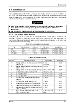


Troubleshooting
Rev. A
5-11
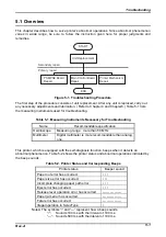
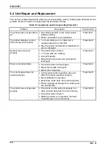
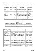
5.3 Repair of C124 PSB/PSE Board
This section describes how to repair the PSB/PSE board to the component. Table 5-8 shows the
abnormal conditions and corresponding causes, check points and solutions. Select the condition
from the table and perform any necessary check and repair.
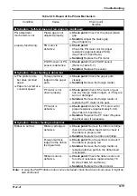
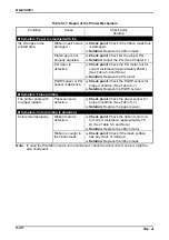
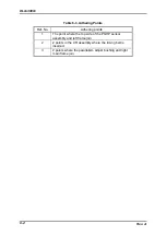
Table 5-8. C124 PSB/PSE Board Repair
Condition
Cause
Check point
Solution
Symptom : Normal voltage is not output.
Fuse is blown
out soon after
replaced.
Line filter circuit
is defective.
Check
C1
to
C4
or L4 for a short circuit
with the AC line.
Replace any
defective
component.
Rectification or
smoothing
circuit is
defective.
Check the followings for short circuit:
−
DB101
−
All (+) terminals between
C111
and
DB101
−
T101
and
T201
(See Note 1.)
Replace the
PSB/PSE
board,
DB101
or any
associated
defective
component.
All output
voltages are
abnormal.
(Due to the
circuit structure,
when the +35 V
Diode bridge
DB101
is
defective.
Check that the voltage output from
pin 3 (+) and pin 4 (-) on DB101 is as
follows:
−
C124 PSB
: Approximately 170V
−
C124 PSE
: Approximately 300V
(See Note 2.)
Replace the
PSB/PSE
board,
DB101
or any
associated
defective
component.
output is
abnormal, all
other output
voltages are
affected.)
Soft start circuit
(surge circuit) is
defective.
Check that DC voltages at the both
ends of R2 and R3 are 0 V.
R2 and R3 are open,
TY101
is bad,
or R124, D103, or
T101
/
201
which
are used to turn on
TY101
is bad.
Replace
PSB/
PSE
board or
any associated
defective
component.
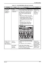
Switching FET
Q101
or
Q201
is
defective.
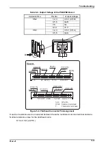
Check for the correct switching
operation of
Q101
/
201
by checking if
the waveform output from pins 6 and
7 of the T101/201 primary coil is
correct, as shown below.
Figure 5-9. Switching Waveform
Replace the
PSB
/
PSE
board,
DB101
or any
associated
defective
component.
Notes:
1.
DB101
is possibly shortened as a result of the short circuit of other components behind
DB101
.
2. Degradation of some component behind
DB101
may suppress the
DB101
output voltage
Summary of Contents for DLQ-3000 Minerva+
Page 1: ...EPSON 24 PIN DOT MATRIX PRINTER EPSON DLQ 3000 SERVICE MANUAL SEIKO EPSON CORPORATION 4008259 ...
Page 5: ...v REVISION SHEET Revision Issued Data Contents Rev A August 21 1997 First Release ...
Page 61: ...2 3 12 Other Sensor Circuits 2 31 ...
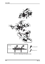
Page 160: ...Chapter 6 Maintenance 6 1 Maintenance 6 1 6 1 1 Lubrication and Adhesion 6 1 ...
Page 171: ...DLQ 3000 Rev A A 6 ...
Page 172: ...Appendix Rev A A 7 A 2 Circuit Diagrams Figure A 2 C210 MAIN Board Circuit Diagram 1 2 ...
Page 173: ...DLQ 3000 Rev A A 8 ...
Page 174: ...Appendix Rev A A 9 Figure A 3 C210 MAIN Board Circuit Diagram 2 2 ...
Page 175: ...DLQ 3000 Rev A A 10 ...
Page 177: ...DLQ 3000 Rev A A 12 Figure A 5 C124 PSB Board Circuit Diagram ...
Page 180: ...Appendix Rev A A 15 Figure A 8 C210 MAIN Board Component Layout 2 2 ...
Page 181: ...DLQ 3000 Rev A A 16 Figure A 9 C124 PSB Board Component Layout ...
Page 182: ...Appendix Rev A A 17 Figure A 10 C124 PSE Board Component Layout ...
Page 189: ...EPSON SEIKO EPSON CORPORATION ...