


DLQ-3000+
Rev. A
2-12
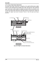
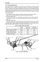
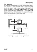
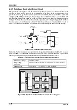
2.1.5.3 Release Mechanism
The release mechanism consists of the release lever, sub release lever, release lever link
and release sensor. It switches the paper path between cut sheet mode (including CSF
mode ), continuous paper mode and paper jam removal mode in accordance with the
release lever setting. It is performed by switching the torque from the PF motor and adding
/releasing pressure toward/from the rollers in the paper feed mechanism. The release lever
shifts the release lever link via the sub release lever to add friction to paper or to release
pressure from the paper.
Cut sheet mode
The torque from the PPF motor is transmitted to the PF mechanism side, where the
paper is fed with friction added by the sub paper loading roller assembly.
Continuous paper mode
The torque from the PF motor is transmitted to the tractor gear via the tractor gear train
to feed continuous paper. The sub paper loading rollers are used to hold and feed the
paper only.
Paper jam removal mode
To set the release lever to this mode releases the paper bail as well as the sub paper
loading rollers. In this full release condition, the jammed paper can be manually ejected
The release sensor detects whether the release mechanism is in the cut sheet mode or
continuous paper mode, and sends the information to the controller circuit.
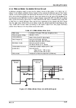
Table 2-8. Release Mechanism Mode
Cut sheet
mode
Continuous
paper mode
Paper jam
removal mode
Paper eject lever assembly
Closed
Open
Open
Paper loading drive roller
Closed
Closed
Open
Tractor transmission gear
and tractor gear condition
Disengaged
Engaged
Engaged
Release sensor state
Open
Closed
Closed
Tractor Transmission Gear
Tractor Gear
Paper Feed Drive Roller
Sub Paper Feed Roller Assembly
Release Link Lever
Paper Bail Roller
Paper Eject Drive Roller Assembly
Release Sensor
Friction Mode
Tractor Mode
Paper Jam Clear Mode
Sub Release Lever
Figure 2-9. Release Mechanism
Summary of Contents for DLQ-3000 Minerva+
Page 1: ...EPSON 24 PIN DOT MATRIX PRINTER EPSON DLQ 3000 SERVICE MANUAL SEIKO EPSON CORPORATION 4008259 ...
Page 5: ...v REVISION SHEET Revision Issued Data Contents Rev A August 21 1997 First Release ...
Page 61: ...2 3 12 Other Sensor Circuits 2 31 ...
Page 160: ...Chapter 6 Maintenance 6 1 Maintenance 6 1 6 1 1 Lubrication and Adhesion 6 1 ...
Page 171: ...DLQ 3000 Rev A A 6 ...
Page 172: ...Appendix Rev A A 7 A 2 Circuit Diagrams Figure A 2 C210 MAIN Board Circuit Diagram 1 2 ...
Page 173: ...DLQ 3000 Rev A A 8 ...
Page 174: ...Appendix Rev A A 9 Figure A 3 C210 MAIN Board Circuit Diagram 2 2 ...
Page 175: ...DLQ 3000 Rev A A 10 ...
Page 177: ...DLQ 3000 Rev A A 12 Figure A 5 C124 PSB Board Circuit Diagram ...
Page 180: ...Appendix Rev A A 15 Figure A 8 C210 MAIN Board Component Layout 2 2 ...
Page 181: ...DLQ 3000 Rev A A 16 Figure A 9 C124 PSB Board Component Layout ...
Page 182: ...Appendix Rev A A 17 Figure A 10 C124 PSE Board Component Layout ...
Page 189: ...EPSON SEIKO EPSON CORPORATION ...