


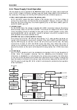


Operating Principles
Rev. A
2-3
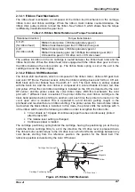
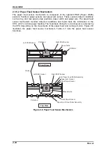
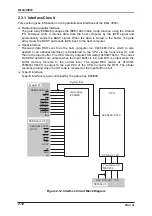
2.1.2 CR (Carriage) Mechanism
The CR mechanism consists of the CR movement mechanism, external cooling fan, and
platen gap adjustment mechanism.
CR movement mechanism
The CR is supported by 2 CR guide shafts by its high and low ends. The stepping motor
used for the CR motor enables the CR to move to any positions. The motor also sends
torque to the timing belt pulley to drive the timing belt. The timing belt with one of the
edges fixed to the head carriage moves the head carriage along the carriage guide shaft
from right to left or vice versa according to the direction the CR motor rotates. Since the
length of the belt is affected by the change in temperature, belt tension spring is
attached to keep the belt with a constant tension. The HP sensor (Home Position sensor)
is located at the reference position (on the right side as seen from the front) in the printer
mechanism. Photo-coupler system used for the sensor detects the CR when the flag of
the CR crosses emission. It is only operated when the printer is turned on, and once it is
detected, CR movement is put under the open-loop control system. After the controller
circuit determines where to move the CR according to the received data, it converts the
distance to the position into the corresponding phase change pulse and outputs it to the
CR motor. If the CR home position is detected during printing or the printer initialization, it
indicates the status that the printer fails to detect the home position at a correct position
and an error occurs as a result. CR speed is controlled by the CR motor drive frequency
which depends on the printing data.
CR
Flag
CR HP Sensor
Bushing
Timing Belt Pulley
External Cooling Fan
Cooling Air
Printhead
Platen
Belt Tension Spring
Timing Belt
Figure 2-2. CR Mechanism
External cooling fans
This printer is equipped with 2 cooling fans. One, located at the left bottom of the printer,
eliminates excess heat from the circuit boards. The other one is externally attached to
the right side of the printer mechanism to blow the air directly to remove excess heat
from the printhead.
Table 2-2. External Cooling Fan Unit Specification
Type
DC brush-less motor (ball bearing built in)
Power supply voltage
35 VDC
±
10 %
Consumption current
0.07 A or less
Rotating speed
3800 rpm or more
Summary of Contents for DLQ-3000 Minerva+
Page 1: ...EPSON 24 PIN DOT MATRIX PRINTER EPSON DLQ 3000 SERVICE MANUAL SEIKO EPSON CORPORATION 4008259 ...
Page 5: ...v REVISION SHEET Revision Issued Data Contents Rev A August 21 1997 First Release ...
Page 61: ...2 3 12 Other Sensor Circuits 2 31 ...
Page 160: ...Chapter 6 Maintenance 6 1 Maintenance 6 1 6 1 1 Lubrication and Adhesion 6 1 ...
Page 171: ...DLQ 3000 Rev A A 6 ...
Page 172: ...Appendix Rev A A 7 A 2 Circuit Diagrams Figure A 2 C210 MAIN Board Circuit Diagram 1 2 ...
Page 173: ...DLQ 3000 Rev A A 8 ...
Page 174: ...Appendix Rev A A 9 Figure A 3 C210 MAIN Board Circuit Diagram 2 2 ...
Page 175: ...DLQ 3000 Rev A A 10 ...
Page 177: ...DLQ 3000 Rev A A 12 Figure A 5 C124 PSB Board Circuit Diagram ...
Page 180: ...Appendix Rev A A 15 Figure A 8 C210 MAIN Board Component Layout 2 2 ...
Page 181: ...DLQ 3000 Rev A A 16 Figure A 9 C124 PSB Board Component Layout ...
Page 182: ...Appendix Rev A A 17 Figure A 10 C124 PSE Board Component Layout ...
Page 189: ...EPSON SEIKO EPSON CORPORATION ...