

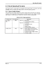


Operating Principles
Rev. A
2-21
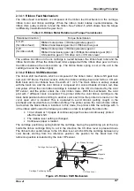
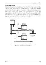
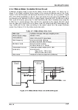
2.3.4 Ribbon Motor Controller/Driver Circuit
A PM-type stepping motor is used for the ribbon motor of this printer. It is driven by 1-1
phase or 2-2 phase excitation mode, based on the selected rotational speed. This motor
rotates in the both forward and backward directions and can stop at any position. Signal
PFA, /PFA, PFB and /PFB are output to drive each phase from the gate array (E05B46) via
the transistor array MP5302. Common voltage change signal (RF_R/H : Run/Hold) is output
from a port of the same gate array. To hold, both faces are driven simultaneously using the
5 VDC line. To switch between Run and Hold is operated by the signals RF_R/H output
from the gate array. While in the color ribbon mode, the printer switches mode between the
copy mode and normal mode according to the signal output from the paper thickness
sensor. See Table 2-11 for the ribbon motor drive term.
Table 2-11. Ribbon Motor Drive Term
Motor type
4 phases / 48-pole / PM-type stepping motor
Power supply voltage
35 VDC
±
10%
Coil resistance
76
Ω
±
10% (at 25°C per phase)
Drive frequency
At color select:460, 600 pps
At ribbon feed:320, 640, 770 pps
Excitation mode
At color select:2-2 phase
At ribbon feed:2-2, 1-1 phase
Consumption current
(mA/motor)
1-fold speed (fabric ribbon):350 - 390
At color select
Copy mode:
550 or less
Normal mode: 400 or less
Drive mode
Constant current uni-polar drive (VPB line)
BP
RFA
RFA
RFB
RFB
B1
B2
B3
B4
RF COM
+5V
CP
C1
C2
C3
C4
EP
VPB(+35V)
RF-R/H
RFA
RFA
RFB
RFB
Gate Array
E05B46
Transistor Array
MP5302
Figure 2-15. Ribbon Motor Driver circuit Block Diagram
Summary of Contents for DLQ-3000 Minerva+
Page 1: ...EPSON 24 PIN DOT MATRIX PRINTER EPSON DLQ 3000 SERVICE MANUAL SEIKO EPSON CORPORATION 4008259 ...
Page 5: ...v REVISION SHEET Revision Issued Data Contents Rev A August 21 1997 First Release ...
Page 61: ...2 3 12 Other Sensor Circuits 2 31 ...
Page 160: ...Chapter 6 Maintenance 6 1 Maintenance 6 1 6 1 1 Lubrication and Adhesion 6 1 ...
Page 171: ...DLQ 3000 Rev A A 6 ...
Page 172: ...Appendix Rev A A 7 A 2 Circuit Diagrams Figure A 2 C210 MAIN Board Circuit Diagram 1 2 ...
Page 173: ...DLQ 3000 Rev A A 8 ...
Page 174: ...Appendix Rev A A 9 Figure A 3 C210 MAIN Board Circuit Diagram 2 2 ...
Page 175: ...DLQ 3000 Rev A A 10 ...
Page 177: ...DLQ 3000 Rev A A 12 Figure A 5 C124 PSB Board Circuit Diagram ...
Page 180: ...Appendix Rev A A 15 Figure A 8 C210 MAIN Board Component Layout 2 2 ...
Page 181: ...DLQ 3000 Rev A A 16 Figure A 9 C124 PSB Board Component Layout ...
Page 182: ...Appendix Rev A A 17 Figure A 10 C124 PSE Board Component Layout ...
Page 189: ...EPSON SEIKO EPSON CORPORATION ...