


DLQ-3000+
Rev. A
2-16
Table 2-10. Main ICs and their Functions
IC
Location
Function
CPU (
H8/3003 equivalent
)
IC16
The main CPU of the controller circuit
Gate Array (E05B46)
IC25
Controls systems and peripheral devices.
Gate Array (E05A89) (built
in the panel circuit board.)
−
Functions as the I/F between the control panel
and controller circuit.
Flash-ROM
IC15
Stores the control program.
PROM
IC18
Stores the control program when the Flash-ROM
is not equipped.
CG (8-Mbit MROM)
IC21
Character generator
CG (4/8-Mbit MROM)
IC24
Character generator
DRAM (
HM514260 equivalent
)
IC26
Manages buffers and work area. (4Mbit)
EEPROM
(AT93C66 equivalent))
IC23
Stores values for default setting, customer data
and so on.
Reset IC (RST592D)
IC22
•
Resets hardware
•
Rests Flash-ROM (Recovery from the reset
condition is done for Flash-ROM prior to the
CPU and gate arrays.)
Reset IC (RST594E)
IC20
•
Reset hardware
•
Resets the CPU and gate arrays.
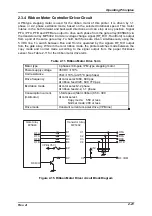
CR motor driver
(SLA7026)
IC7
Drives the CR motor by constant current/uni-polar
drive.
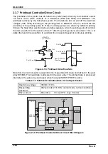
PF motor driver
(SLA7024M)
IC6
Drives the PF motor by constant current/uni-polar
drive.
Ribbon driver (MP5320)
QM2
Drives the ribbon motor on the CR by constant
current/uni-polar drive.
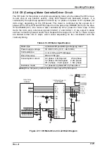
PG motor (SDC03-V1)
QM1
Drives the PG motor by constant current/uni-polar
drive.
Serial I/F transceiver IC
(MAX232CWE)
IC14
Transceiver circuit for the serial I/F
Shunt regulator (TL431)
IC19
Produces the reference voltage (power supply for
the stabilizing the +5V) for the A/D converter.
3-terminal regulator
(LM75L12)
IC17
Stabilizes 12V power supply voltage for head
pre-drive.
Summary of Contents for DLQ-3000 Minerva+
Page 1: ...EPSON 24 PIN DOT MATRIX PRINTER EPSON DLQ 3000 SERVICE MANUAL SEIKO EPSON CORPORATION 4008259 ...
Page 5: ...v REVISION SHEET Revision Issued Data Contents Rev A August 21 1997 First Release ...
Page 61: ...2 3 12 Other Sensor Circuits 2 31 ...
Page 160: ...Chapter 6 Maintenance 6 1 Maintenance 6 1 6 1 1 Lubrication and Adhesion 6 1 ...
Page 171: ...DLQ 3000 Rev A A 6 ...
Page 172: ...Appendix Rev A A 7 A 2 Circuit Diagrams Figure A 2 C210 MAIN Board Circuit Diagram 1 2 ...
Page 173: ...DLQ 3000 Rev A A 8 ...
Page 174: ...Appendix Rev A A 9 Figure A 3 C210 MAIN Board Circuit Diagram 2 2 ...
Page 175: ...DLQ 3000 Rev A A 10 ...
Page 177: ...DLQ 3000 Rev A A 12 Figure A 5 C124 PSB Board Circuit Diagram ...
Page 180: ...Appendix Rev A A 15 Figure A 8 C210 MAIN Board Component Layout 2 2 ...
Page 181: ...DLQ 3000 Rev A A 16 Figure A 9 C124 PSB Board Component Layout ...
Page 182: ...Appendix Rev A A 17 Figure A 10 C124 PSE Board Component Layout ...
Page 189: ...EPSON SEIKO EPSON CORPORATION ...