


DLQ-3000+
Rev. A
2-26
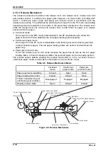
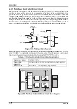
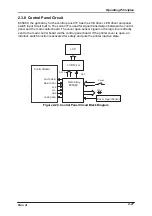
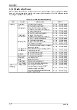
2.3.7 Printhead Controller/Driver Circuit
The printhead of this printer has 24 head coils (12X2 lines) driven by the constant current
coil driver circuit which consists of 2 transistors (PNP and NPN) and MOSFET. The
printhead is driven by the flat wheel system. The transistors turn on and off the head coil
voltages (VPA, VPB) according to the printing pulse A. MOSFET turns on and off the GP
according to the printing pulse B. If the 2 printing pulses are driven by different printing
timings, the head drive waveform shown bellow appears, since the printing pulse B controls
the drive waveform for the period of time “T” after the printing pulse A was driven. This is to
adjust the head drive waveform to avoid decline in respond speed at continuous printing.
V P A / V P B
( 3 1 . 5 ~ 3 8 . 5 V )
T
P r i n t P u l s e A
P r i n t P u l s e B
H e a d C o i l
H e a d C o i l D r i v e
W a v e f o r m
P r i n t P u l s e A
P r i n t P u l s e B
Figure 2-18. Printhead Drive Waveform
Data from the host computer is expanded into image data (CG data) and latched in the gate
array E05B46. The head data is allocated in the gate array. The latched data is processed
internally in the gate array and output while the signal NHPW/PHPW is active.
Table 2-17. Printhead Controller/Driver Circuit Specification
Head drive voltage
35 VDC
±
10%
Responding
waveform
462 seconds (2.16 KHz, normal mode, normal condition)
Drive current
Peak time:
3.3 A (at 5°C, copy 2 mode)
CPU
E05B46
Pre-
Driver
HWR
LWR
ADRESS/
DATA BUS
VPA/VPB
(QM3,4)
(QM5-10)
(IC1-4)
(Q6-33)
NHD01-24
PHD01-14
Printhead
Control Board
Pre-
Driver
Printhead
Driver
Printhead
Driver
Figure 2-19. Printhead Controller/Driver Circuit Block Diagram
Summary of Contents for DLQ-3000 Minerva+
Page 1: ...EPSON 24 PIN DOT MATRIX PRINTER EPSON DLQ 3000 SERVICE MANUAL SEIKO EPSON CORPORATION 4008259 ...
Page 5: ...v REVISION SHEET Revision Issued Data Contents Rev A August 21 1997 First Release ...
Page 61: ...2 3 12 Other Sensor Circuits 2 31 ...
Page 160: ...Chapter 6 Maintenance 6 1 Maintenance 6 1 6 1 1 Lubrication and Adhesion 6 1 ...
Page 171: ...DLQ 3000 Rev A A 6 ...
Page 172: ...Appendix Rev A A 7 A 2 Circuit Diagrams Figure A 2 C210 MAIN Board Circuit Diagram 1 2 ...
Page 173: ...DLQ 3000 Rev A A 8 ...
Page 174: ...Appendix Rev A A 9 Figure A 3 C210 MAIN Board Circuit Diagram 2 2 ...
Page 175: ...DLQ 3000 Rev A A 10 ...
Page 177: ...DLQ 3000 Rev A A 12 Figure A 5 C124 PSB Board Circuit Diagram ...
Page 180: ...Appendix Rev A A 15 Figure A 8 C210 MAIN Board Component Layout 2 2 ...
Page 181: ...DLQ 3000 Rev A A 16 Figure A 9 C124 PSB Board Component Layout ...
Page 182: ...Appendix Rev A A 17 Figure A 10 C124 PSE Board Component Layout ...
Page 189: ...EPSON SEIKO EPSON CORPORATION ...