


DLQ-3000+
Rev. A
5-16
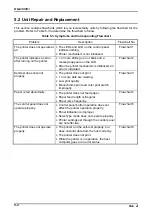
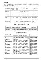
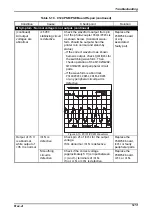
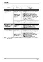
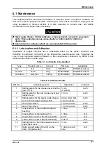
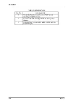
Table 5-13. Repair of C210 MAIN Board (continued)
Condition
Cause
Check point
Solution
Symptom : Abnormal printing
Printhead
control circuit
operates
abnormally.
Printhead control
circuit is
defective.
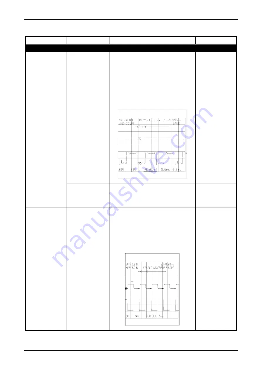
If some particular dots are missing or
bad, check which head driver is
causing the problem, the driver for
print pulse A or B.
−
If any of the drivers is bad, see the
circuit diagram and replace the
corresponding drive transistors (
Q6
to
Q33
,
QM3
to
QM10
). (See Note 1.)
−
If both drivers are good, gate array
IC25
is defective.
Figure 5-14. Head Drive Signal Waveform
Replace the
main control
board or
associated
component.
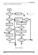
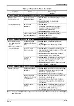
Printhead driver
circuit is
defective.
Check pin 3 of 3-terminal regulator
IC17
for the correct output voltage
(+12
V).
If it’s correct, gate array
IC25
is
defective.
Replace the
main control
board or any
associated part.
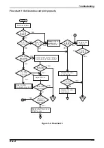
PG motor is not
functioning
properly.
PG motor driver
circuit is
defective.
Check pins 1,3,5,and 7 of
QM1
for the
input signal waveform and pins
15/16, 13/14, 11/12 and 9/10 of
QM1
for output signal waveform.
−
If no motor phase input signals is
input, gate array
IC25
is defective.
−
If no drive waveforms is output,
QM1
is defective.
Figure 5-15. PG Motor Drive waveform
Replace the
main control
board or any
associated
parts.
Note:
1.
HD
-No. shown in the diagram and corresponding dot No. are the same.
Summary of Contents for DLQ-3000 Minerva+
Page 1: ...EPSON 24 PIN DOT MATRIX PRINTER EPSON DLQ 3000 SERVICE MANUAL SEIKO EPSON CORPORATION 4008259 ...
Page 5: ...v REVISION SHEET Revision Issued Data Contents Rev A August 21 1997 First Release ...
Page 61: ...2 3 12 Other Sensor Circuits 2 31 ...
Page 160: ...Chapter 6 Maintenance 6 1 Maintenance 6 1 6 1 1 Lubrication and Adhesion 6 1 ...
Page 171: ...DLQ 3000 Rev A A 6 ...
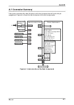
Page 172: ...Appendix Rev A A 7 A 2 Circuit Diagrams Figure A 2 C210 MAIN Board Circuit Diagram 1 2 ...
Page 173: ...DLQ 3000 Rev A A 8 ...
Page 174: ...Appendix Rev A A 9 Figure A 3 C210 MAIN Board Circuit Diagram 2 2 ...
Page 175: ...DLQ 3000 Rev A A 10 ...
Page 177: ...DLQ 3000 Rev A A 12 Figure A 5 C124 PSB Board Circuit Diagram ...
Page 180: ...Appendix Rev A A 15 Figure A 8 C210 MAIN Board Component Layout 2 2 ...
Page 181: ...DLQ 3000 Rev A A 16 Figure A 9 C124 PSB Board Component Layout ...
Page 182: ...Appendix Rev A A 17 Figure A 10 C124 PSE Board Component Layout ...
Page 189: ...EPSON SEIKO EPSON CORPORATION ...