


DLQ-3000+
Rev. A
1-24
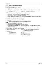
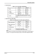
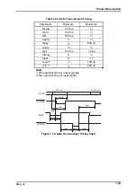
3. Forms-override printing is available for 20 lines after the paper end is detected.
(Paper feeding pitch is not guaranteed.) The end of the printable are is 4.2 mm or
more apart from the bottom edge of the paper
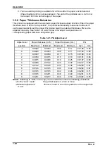
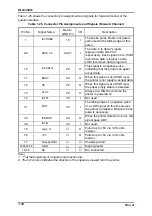
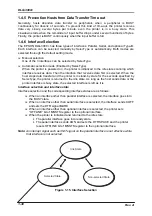
1.3.6 Paper Thickness Detection
This printer is equipped with the automatic paper thickness adjust function. When the paper
thickness lever is set to “Auto position”, the printer automatically measures thickness of
each paper loaded to set the proper PG (platen Gap) the detected thickness. PG is also
adjusted manually. See Table 1-21 which shows the adjust lever position and
corresponding paper thickness and platen gap.
Table 1-21. PG Adjust Lever
Adjust lever
Paper thickness (inch)
Paper thickness (mm)
PG
position
Maximum
Minimum
Maximum
Minimum
Inch
mm
-1
0.0024
0.0043
0.06
0.11
0.0138
0.35
0
0.0024
0.0043
0.06
0.11
0.0154
0.39
1
0.0043
0.0059
0.11
0.15
0.0169
0.43
2
0.0059
0.0075
0.15
0.19
0.0181
0.46
3
0.0075
0.0098
0.19
0.25
0.0197
0.50
4
0.0098
0.0122
0.25
0.30
0.0217
0.55
5
0.0122
0.0146
0.30
0.36
0.0240
0.61
6
0.0146
0.0165
0.36
0.42
0.0264
0.67
7
0.0165
0.0185
0.42
0.46
0.0280
0.71
8
0.0185
0.0201
0.46
0.49
0.0291
0.74
9
0.0201
0.0217
0.49
0.53
0.0307
0.78
Notes: Switching to “Dark” in the copy mode is effective under the following conditions:
In the “Auto” mode:
Paper thickness is 0.2 mm or more.
Manual adjustment:
The lever is set to one of the positions in the range from
3 to 9.
Summary of Contents for DLQ-3000 Minerva+
Page 1: ...EPSON 24 PIN DOT MATRIX PRINTER EPSON DLQ 3000 SERVICE MANUAL SEIKO EPSON CORPORATION 4008259 ...
Page 5: ...v REVISION SHEET Revision Issued Data Contents Rev A August 21 1997 First Release ...
Page 61: ...2 3 12 Other Sensor Circuits 2 31 ...
Page 160: ...Chapter 6 Maintenance 6 1 Maintenance 6 1 6 1 1 Lubrication and Adhesion 6 1 ...
Page 171: ...DLQ 3000 Rev A A 6 ...
Page 172: ...Appendix Rev A A 7 A 2 Circuit Diagrams Figure A 2 C210 MAIN Board Circuit Diagram 1 2 ...
Page 173: ...DLQ 3000 Rev A A 8 ...
Page 174: ...Appendix Rev A A 9 Figure A 3 C210 MAIN Board Circuit Diagram 2 2 ...
Page 175: ...DLQ 3000 Rev A A 10 ...
Page 177: ...DLQ 3000 Rev A A 12 Figure A 5 C124 PSB Board Circuit Diagram ...
Page 180: ...Appendix Rev A A 15 Figure A 8 C210 MAIN Board Component Layout 2 2 ...
Page 181: ...DLQ 3000 Rev A A 16 Figure A 9 C124 PSB Board Component Layout ...
Page 182: ...Appendix Rev A A 17 Figure A 10 C124 PSE Board Component Layout ...
Page 189: ...EPSON SEIKO EPSON CORPORATION ...