


Product Description
Rev. A
1-39
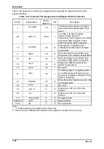
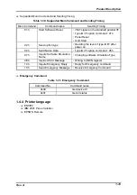
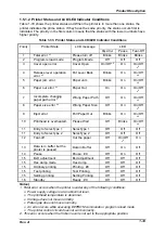
1.5.1.2 Printer Status and LCD/LED Indicator Conditions
Table 1-33 shows the printer status and When the printer is in more than one status, the
printer indicates the prime status. If they have the same priority, the status occurs first is
indicated. The priority in the first column means that the status with the lower numbers have
higher priority.
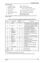
Table 1-33. Printer Status and LCD/LED Indicator Conditions
Priority
Printer State
LCD message
LED
Paper Out
Pause
Tear-Off
1
Fatal error *
1
Please turn off
Blinks
Blinks
Blinks
2
Program reload mode
Program Mode
Off
Off
Off
3
Cover open error
Cover Open
On/Off *
6
On
On/Off
*
6
4
Release lever operation
error *
2
Put Lever Back
Blinks
On
On/Off
*
6
5
Paper jam error
Paper Jam
Blinks
On
On/Off
*
6
6
Paper out error *
3
Paper Out
On
On
On/Off
*
6
7
Incomplete changing
paper path error *
4
Wrong Paper Path
Off
On
On/Off
*
6
8
Paper size error *
5
Wrong Paper Size
Off
On
On/Off
*
6
9
Eject error
Pull Paper Out
Blinks
On
On/Off
*
6
10
Printhead is overheated.
Please Wait
Off
Blinks
On/Off
*
6
11
Entry to SelecType 1
SelecType 1
Off
Off
Off
11
Entry to SelecType 2
SelecType 2
Off
Off
Off
12
Tear-off
Cut the paper
Off
On/Off
*
6
On
13
Data is in buffer but the
printer is paused
Data in Buffer
Off
On
Off
14
Pause
Pause : #0
Off
On
Off
15
Bi-D adjustment
Bi-d adjustment
Off
Off
Off
15
Hex dump mode
Hex dump
Off
Off
Off
15
Ordinary printing
Printing : #0
Off
Off
Off
15
Test printing
Test Printing
Off
Off
Off
15
Setting printing
Setting Printing
Off
Off
Off
16
Standby
Ready : #0
Off
Off
Off
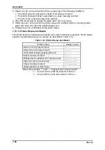
Notes)
1. Fatal error occurs when the printer is under any of the following conditions:
•
Power supply voltage is at an abnormal level.
•
The printhead temperature is abnormal.
•
Carriage does not move normally.
•
Platen gap does not move normally.
•
An error occurs while executing EEPROM commands or program reload mode.
•
The printer control circuit does not work correctly.
2. This error occurs when the friction lever is not set to the appropriate position.
Summary of Contents for DLQ-3000 Minerva+
Page 1: ...EPSON 24 PIN DOT MATRIX PRINTER EPSON DLQ 3000 SERVICE MANUAL SEIKO EPSON CORPORATION 4008259 ...
Page 5: ...v REVISION SHEET Revision Issued Data Contents Rev A August 21 1997 First Release ...
Page 61: ...2 3 12 Other Sensor Circuits 2 31 ...
Page 160: ...Chapter 6 Maintenance 6 1 Maintenance 6 1 6 1 1 Lubrication and Adhesion 6 1 ...
Page 171: ...DLQ 3000 Rev A A 6 ...
Page 172: ...Appendix Rev A A 7 A 2 Circuit Diagrams Figure A 2 C210 MAIN Board Circuit Diagram 1 2 ...
Page 173: ...DLQ 3000 Rev A A 8 ...
Page 174: ...Appendix Rev A A 9 Figure A 3 C210 MAIN Board Circuit Diagram 2 2 ...
Page 175: ...DLQ 3000 Rev A A 10 ...
Page 177: ...DLQ 3000 Rev A A 12 Figure A 5 C124 PSB Board Circuit Diagram ...
Page 180: ...Appendix Rev A A 15 Figure A 8 C210 MAIN Board Component Layout 2 2 ...
Page 181: ...DLQ 3000 Rev A A 16 Figure A 9 C124 PSB Board Component Layout ...
Page 182: ...Appendix Rev A A 17 Figure A 10 C124 PSE Board Component Layout ...
Page 189: ...EPSON SEIKO EPSON CORPORATION ...