


DLQ-3000+
Rev. A
3-8
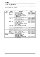
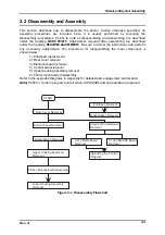
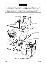
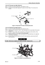
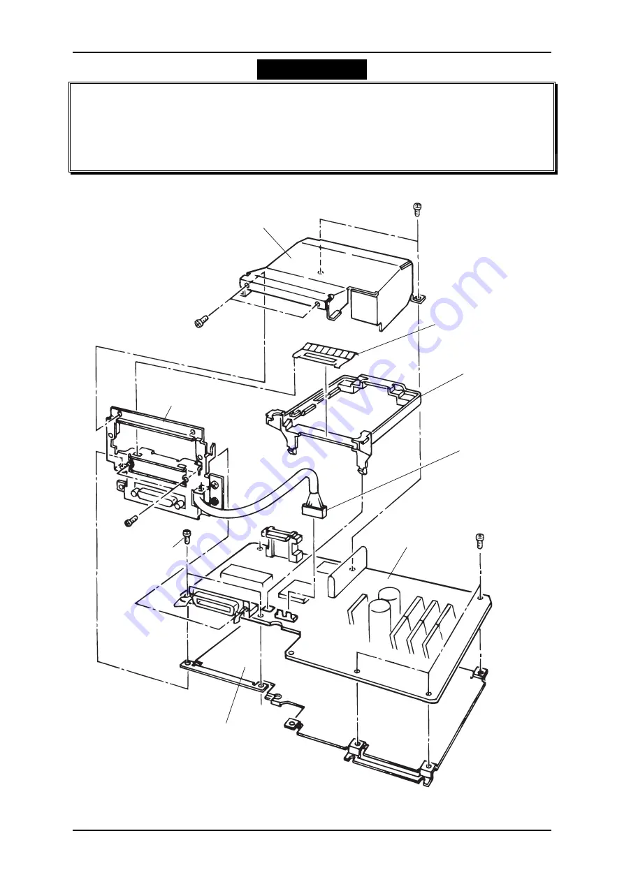
WORK POINT
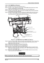
When connecting the connectors, connect one to the other of the same color. Pay
special attention to CN1 (red harness) and CN2 (blue harness). If they are
connected improperly, the head coil or C210 MAIN board may be damaged. (See
Figure 3-5.)
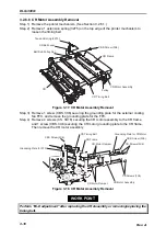
Perform “Control program reload” and any necessary adjustments when C210
MAIN board is replaced. (Refer to Section 3.3. and Chapter 4 “Adjustment”.)
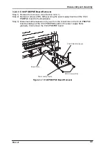
T y p e - B S h i e l d C a s e
E a r t h S p r i n g ( B )
I / F B o a r d G u i d e
I / F G r o u n d i n g P l a t e
( C N 8 )
C B S S c r e w s ( 3 X 6 )
C B S S c r e w ( 3 X 6 )
C B S S c r e w s ( 3 X 6 )
C B S S c r e w s
( 3 X 6 )
C 2 1 0 M A I N
C P S c r e w s
( 3 X 6 )
H a r n e s s f o r t h e
S r i a l I / F
M a i n F r a m e
Figure 3-6. C210 MAIN Board Removal
Summary of Contents for DLQ-3000 Minerva+
Page 1: ...EPSON 24 PIN DOT MATRIX PRINTER EPSON DLQ 3000 SERVICE MANUAL SEIKO EPSON CORPORATION 4008259 ...
Page 5: ...v REVISION SHEET Revision Issued Data Contents Rev A August 21 1997 First Release ...
Page 61: ...2 3 12 Other Sensor Circuits 2 31 ...
Page 160: ...Chapter 6 Maintenance 6 1 Maintenance 6 1 6 1 1 Lubrication and Adhesion 6 1 ...
Page 171: ...DLQ 3000 Rev A A 6 ...
Page 172: ...Appendix Rev A A 7 A 2 Circuit Diagrams Figure A 2 C210 MAIN Board Circuit Diagram 1 2 ...
Page 173: ...DLQ 3000 Rev A A 8 ...
Page 174: ...Appendix Rev A A 9 Figure A 3 C210 MAIN Board Circuit Diagram 2 2 ...
Page 175: ...DLQ 3000 Rev A A 10 ...
Page 177: ...DLQ 3000 Rev A A 12 Figure A 5 C124 PSB Board Circuit Diagram ...
Page 180: ...Appendix Rev A A 15 Figure A 8 C210 MAIN Board Component Layout 2 2 ...
Page 181: ...DLQ 3000 Rev A A 16 Figure A 9 C124 PSB Board Component Layout ...
Page 182: ...Appendix Rev A A 17 Figure A 10 C124 PSE Board Component Layout ...
Page 189: ...EPSON SEIKO EPSON CORPORATION ...