


Operating Principles
Rev. A
2-13
2.2 Circuit Operating Principles
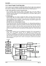
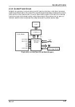
The power source of this printer is composed of the power switch, AC cable and C124
PSB/PSE board. It supplies DC voltage used to control the printer operation.
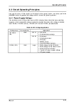
2.2.1 Power Supply Voltage
The electrical circuit of this printer uses an RCC (ringing choke converter) type switching
regulator, which outputs DC voltage required to operate the printer. DC voltage is divided
into 3 blocks: +35 VDC (CH. A), +35 VDC (CH. B) and +5 VDC, as listed below.
Table 2-9. DC Voltage Application
Voltage level
Connector No.
Application
+35 VDC
±
10%
CN2
CH. A
•
CR motor
•
Printhead drive voltage
CH. B
•
Printhead
•
Cooling fan motor
•
PF motor
•
Ribbon motor
•
Vpp of the flush memory
+5 VDC
±
5%
CN3
Logic
•
Hold voltage for the PF motor
•
Hold voltage for the ribbon motor
•
Serial I/F level converter
•
Type-B I/F power supply voltage
•
I/F power supply
Summary of Contents for DLQ-3000 Minerva+
Page 1: ...EPSON 24 PIN DOT MATRIX PRINTER EPSON DLQ 3000 SERVICE MANUAL SEIKO EPSON CORPORATION 4008259 ...
Page 5: ...v REVISION SHEET Revision Issued Data Contents Rev A August 21 1997 First Release ...
Page 61: ...2 3 12 Other Sensor Circuits 2 31 ...
Page 160: ...Chapter 6 Maintenance 6 1 Maintenance 6 1 6 1 1 Lubrication and Adhesion 6 1 ...
Page 171: ...DLQ 3000 Rev A A 6 ...
Page 172: ...Appendix Rev A A 7 A 2 Circuit Diagrams Figure A 2 C210 MAIN Board Circuit Diagram 1 2 ...
Page 173: ...DLQ 3000 Rev A A 8 ...
Page 174: ...Appendix Rev A A 9 Figure A 3 C210 MAIN Board Circuit Diagram 2 2 ...
Page 175: ...DLQ 3000 Rev A A 10 ...
Page 177: ...DLQ 3000 Rev A A 12 Figure A 5 C124 PSB Board Circuit Diagram ...
Page 180: ...Appendix Rev A A 15 Figure A 8 C210 MAIN Board Component Layout 2 2 ...
Page 181: ...DLQ 3000 Rev A A 16 Figure A 9 C124 PSB Board Component Layout ...
Page 182: ...Appendix Rev A A 17 Figure A 10 C124 PSE Board Component Layout ...
Page 189: ...EPSON SEIKO EPSON CORPORATION ...