


DLQ-3000+
Rev. A
2-6
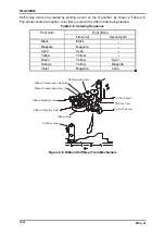
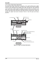
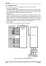
2.1.4 Ribbon Feed/Ribbon Shift Mechanism
Ribbon feed/ribbon shift mechanism, located at the upper part of the CR, is composed of
the ribbon motor, ribbon wind-up mechanism inside the ribbon cartridge, ribbon shift
mechanism, and color ribbon cartridge sensor. The torque from the ribbon motor, the only
motor which drives these mechanisms, is transmitted to each mechanism by changing the
direction for rotating the motor, as described below:
Forward rotation (Clockwise):
Color/Black ribbon shift
Backward rotation (Counterclockwise):
Ribbon feed
A stepping motor used for the ribbon motor enables the CR to move to and stop at any
position. The color ribbon cartridge sensor detects which of color or black ribbon cartridge is
installed and switches the ribbon motor between the monochrome ribbon mode and color
ribbon mode according detected cartridge. The printer refers to the switch mode of the
sensor when the printer is turned on or resuming the operation after the cover open error is
detected. The motor is controlled by the open-loop system. While the motor is used for the
ribbon shift, the color home position sensor detects the reference position (black) to
manage the color ribbon shift. The motor drive speed and phase excitement mode changes
in accordance with printing modes such as copy mode, normal mode and color mode.
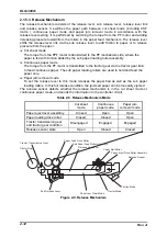
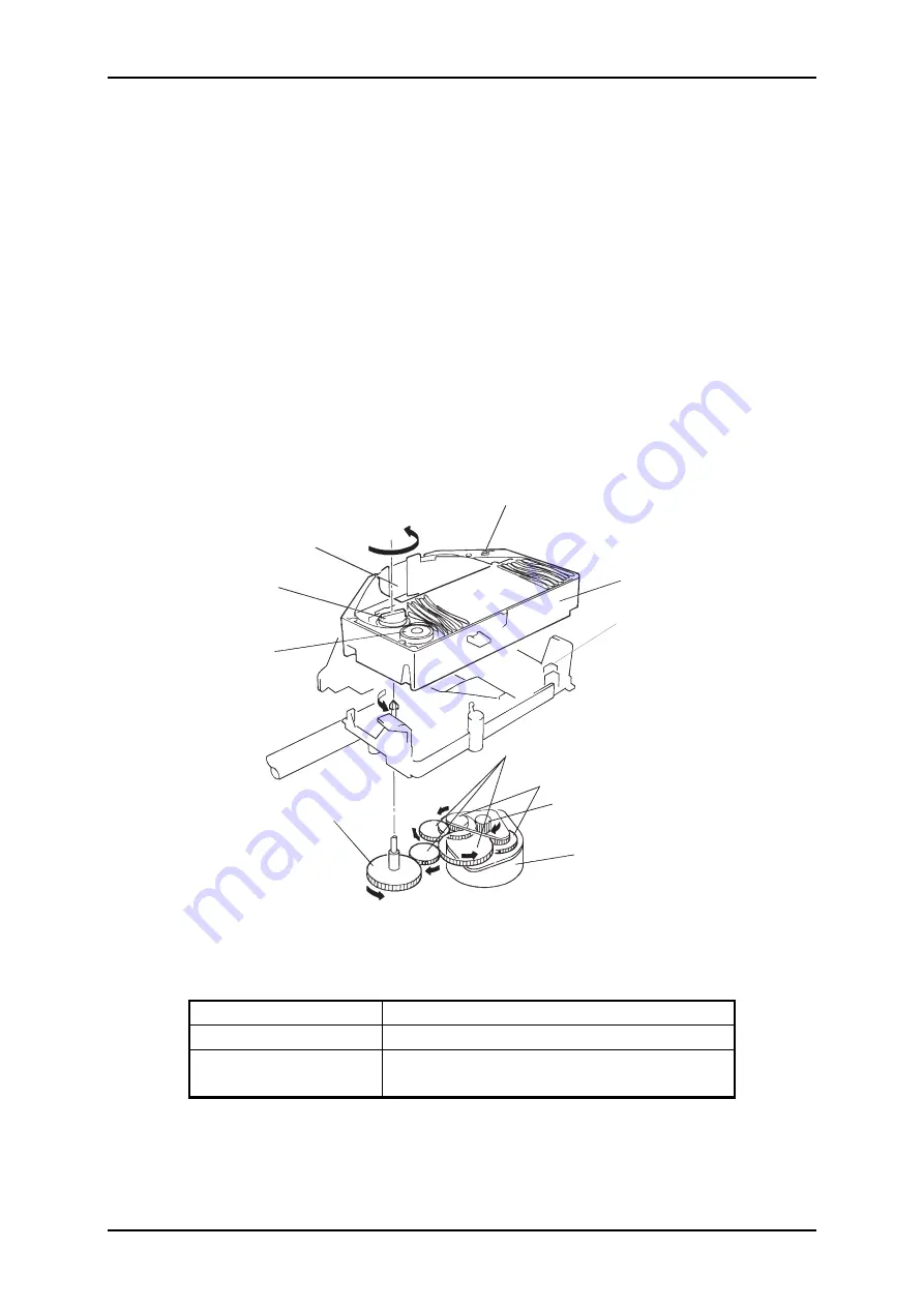
R i b b o n B r a k e S p r i n g
R i b b o n C a r t r i d g e
C o l o r R i b b o n C a r t r i d g e
S e n s o r
C R / P F P i n i o n
R i b b o n M o t o r
R i b b o n D r i v e G e a r
R i b b o n H o l d R o l l e r
R i b b o n F e e d R o l l e r
I n k R i b b o n
R i b b o n T r a n s m i s s i o n G e a r T r a i n
R i b b o n P l a n e t a r y g e a r
Figure 2-4. Ribbon Feed/Ribbon Shift Mechanism
Table 2-4. Color Ribbon Cartridge Sensor Specification
Detecting method
Mechanical switch system
Rated voltage/current
5 to 10 mA/5 VDC ± 5%
Switch mode
Monochrome ribbon mode : HIGH
Color ribbon mode:
LOW
Summary of Contents for DLQ-3000 Minerva+
Page 1: ...EPSON 24 PIN DOT MATRIX PRINTER EPSON DLQ 3000 SERVICE MANUAL SEIKO EPSON CORPORATION 4008259 ...
Page 5: ...v REVISION SHEET Revision Issued Data Contents Rev A August 21 1997 First Release ...
Page 61: ...2 3 12 Other Sensor Circuits 2 31 ...
Page 160: ...Chapter 6 Maintenance 6 1 Maintenance 6 1 6 1 1 Lubrication and Adhesion 6 1 ...
Page 171: ...DLQ 3000 Rev A A 6 ...
Page 172: ...Appendix Rev A A 7 A 2 Circuit Diagrams Figure A 2 C210 MAIN Board Circuit Diagram 1 2 ...
Page 173: ...DLQ 3000 Rev A A 8 ...
Page 174: ...Appendix Rev A A 9 Figure A 3 C210 MAIN Board Circuit Diagram 2 2 ...
Page 175: ...DLQ 3000 Rev A A 10 ...
Page 177: ...DLQ 3000 Rev A A 12 Figure A 5 C124 PSB Board Circuit Diagram ...
Page 180: ...Appendix Rev A A 15 Figure A 8 C210 MAIN Board Component Layout 2 2 ...
Page 181: ...DLQ 3000 Rev A A 16 Figure A 9 C124 PSB Board Component Layout ...
Page 182: ...Appendix Rev A A 17 Figure A 10 C124 PSE Board Component Layout ...
Page 189: ...EPSON SEIKO EPSON CORPORATION ...