


Adjustment
Rev. A
4-3
4.2.1.1 Parallelism Adjustment
Step 1) Remove the upper housing assembly. (See Section 3.2.5.)
Step 2) Remove the printhead. (See Section 3.2.1.1.)
Step 3) Remove the ribbon mask. (See Section 3.2.1.2.)
Step 4) Reinstall the prnthead.
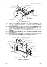
Step 5) Open the paper eject lever assembly. Loosen 2 screws (CBS, 3x6 and CP (O),
3x10) securing the lower CR guide lever to the right frame enough to move the
lever. (See Figure 3-26 in Chapter 3.)
Step 6) Slide the CR unit to the left end.
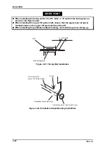
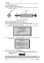
Step 7) Turn the CR guide shaft forward until the thickness gauge (0.39 mm) fits in
between the platen roller and the printhead.
Step 8) Slide the CR to the right end.
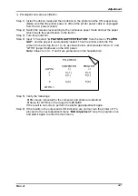
Step 9) Turn the parallelism adjust bushing so that the PG meets the following
specification:
Specification:
The thickness gauge (0.37 mm or 0.41 mm) fits in between
the platen roller and the printhead, and it can be removed
with a little force (50 fg).
Step 10) Repeat the steps from 6 to 9 until the printhead and the platen roller are parallel
with the difference of 0.02 mm or less between the right and left ends of the roller.
Step 11) Fasten the screw when the adjustment is accomplished.
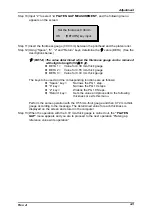
When this adjustment is made, you are to proceed to the next operation “Platen gap
reference value measurement and write”.
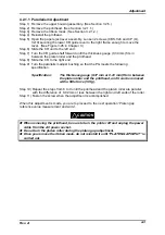
When removing the printhead, be sure to turn the printer off and unplug the power
cable from the AC power socket.
Do not turn the platen roller during the platen gap adjustment.
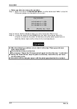
Once you remove the ribbon mask, do not reinstall it until “PLATEN GAP INPUT” is
carried out.
CAUTION
Summary of Contents for DLQ-3000 Minerva+
Page 1: ...EPSON 24 PIN DOT MATRIX PRINTER EPSON DLQ 3000 SERVICE MANUAL SEIKO EPSON CORPORATION 4008259 ...
Page 5: ...v REVISION SHEET Revision Issued Data Contents Rev A August 21 1997 First Release ...
Page 61: ...2 3 12 Other Sensor Circuits 2 31 ...
Page 160: ...Chapter 6 Maintenance 6 1 Maintenance 6 1 6 1 1 Lubrication and Adhesion 6 1 ...
Page 171: ...DLQ 3000 Rev A A 6 ...
Page 172: ...Appendix Rev A A 7 A 2 Circuit Diagrams Figure A 2 C210 MAIN Board Circuit Diagram 1 2 ...
Page 173: ...DLQ 3000 Rev A A 8 ...
Page 174: ...Appendix Rev A A 9 Figure A 3 C210 MAIN Board Circuit Diagram 2 2 ...
Page 175: ...DLQ 3000 Rev A A 10 ...
Page 177: ...DLQ 3000 Rev A A 12 Figure A 5 C124 PSB Board Circuit Diagram ...
Page 180: ...Appendix Rev A A 15 Figure A 8 C210 MAIN Board Component Layout 2 2 ...
Page 181: ...DLQ 3000 Rev A A 16 Figure A 9 C124 PSB Board Component Layout ...
Page 182: ...Appendix Rev A A 17 Figure A 10 C124 PSE Board Component Layout ...
Page 189: ...EPSON SEIKO EPSON CORPORATION ...