


DLQ-3000+
Rev. A
5-10
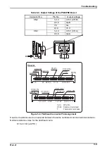
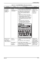
Use a multimeter to check the motor coil resistance and transistor continuity, as shown in Table 5-
5, Table 5-6 and Table 5-7.
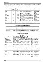
Table 5-5. Motor Coil Resistance
Connector No.
Common
pin No.
Test pin
No.
Test method
Normal value
CN4
(CR motor)
5,6
1,2,3,4
Place 1 lead on pin 5 or pin 6,
and set the other on each
terminal of the 4 phases.
Approximately
1.1
Ω
(at 25° C)
CN4
(PF motor)
17
13,14,
15,16
Place 1 lead on pin 17, and set
the other to each terminal on the
4 phases.
Approximately
5.0
Ω
(at 25° C)
CN4
(PG motor)
7,8
9,10,
11,12
Place 1 lead on pins 7 and 8, and
set the other on each terminal of
the 4 phases.
Approximately
250
Ω
(at 25° C)
CN3
(Ribbon motor)
7
8, 9,
10, 11
Place 1 lead on pin 7, and set the
other to each terminal on the 4
phases.
Approximately
76
Ω
(at 25° C)
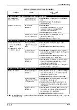
Table 5-6. Printhead Driver Test Point
Transistor No.
Test method
(With the printer power off, and set the
multimeter to
Ω
or diode check mode.)
Meter reading
Q6 to Q33
Connect the leads to the base and collector
or emitter, then reverse the lead.
Neither open or close
completely.
Table 5-7. Sensor Test Point
Sensor connector
No.
Test method
(With the printer power off, and set the
multimeter to
Ω
or diode check mode.)
Meter reading
CN3
(Color ribbon
cartridge sensor)
Place 1 lead on pin 13 and the other on the
ground; then install the color ribbon cartridge
to the CR unit.
Meter should toggle
between open and
short.
CN3
(Rear paper sensor)
Place 1 lead on pin 16 and the other on the
ground; then activate the sensor actuator.
Meter should toggle
between open and
short.
CN5
(PGHP sensor)
Place 1 lead on pin 22 and the other on the
ground; then activate the sensor actuator.
Meter should toggle
between open and
short.
CN5
(Release sensor)
Place 1 lead on pin 20 and the other on the
ground; then change the release lever setting.
Meter should toggle
between open and
short.
CN5
(Adjust switch)
Place 1 lead on one of the pins from 9 to 12
and the other on the ground; then change the
adjust switch setting.
Meter should toggle
between open and
short.
CN14
(Interlock switch)
Place 1 lead on pin 1 and the other on the pin
2; then open and close the printer cover.
Meter should toggle
between open and
short.
Summary of Contents for DLQ-3000 Minerva+
Page 1: ...EPSON 24 PIN DOT MATRIX PRINTER EPSON DLQ 3000 SERVICE MANUAL SEIKO EPSON CORPORATION 4008259 ...
Page 5: ...v REVISION SHEET Revision Issued Data Contents Rev A August 21 1997 First Release ...
Page 61: ...2 3 12 Other Sensor Circuits 2 31 ...
Page 160: ...Chapter 6 Maintenance 6 1 Maintenance 6 1 6 1 1 Lubrication and Adhesion 6 1 ...
Page 171: ...DLQ 3000 Rev A A 6 ...
Page 172: ...Appendix Rev A A 7 A 2 Circuit Diagrams Figure A 2 C210 MAIN Board Circuit Diagram 1 2 ...
Page 173: ...DLQ 3000 Rev A A 8 ...
Page 174: ...Appendix Rev A A 9 Figure A 3 C210 MAIN Board Circuit Diagram 2 2 ...
Page 175: ...DLQ 3000 Rev A A 10 ...
Page 177: ...DLQ 3000 Rev A A 12 Figure A 5 C124 PSB Board Circuit Diagram ...
Page 180: ...Appendix Rev A A 15 Figure A 8 C210 MAIN Board Component Layout 2 2 ...
Page 181: ...DLQ 3000 Rev A A 16 Figure A 9 C124 PSB Board Component Layout ...
Page 182: ...Appendix Rev A A 17 Figure A 10 C124 PSE Board Component Layout ...
Page 189: ...EPSON SEIKO EPSON CORPORATION ...