


DLQ-3000+
Rev. A
1-18
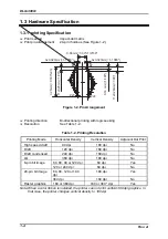
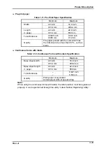
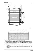
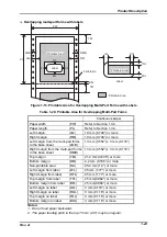
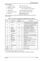
Continuous paper
P W
R M
B M
P L
T M
L M
P e r f o r a t i o n
P e r f o r a t i o n
P r i n t a b l e A r e a
Figure 1-8. Printable Area for Continuous Paper
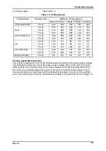
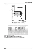
Continuous paper
Paper width
(PW)
Refer to Section 1.3.4.
Paper length
(PL)
Refer to Section 1.3.4.
Left margin
(PM)
9 mm (0.354”) or more
Right margin
(LM)
9 mm (0.354”) or more
Top margin
(TM)
4.2 mm (0.165”) or more
Bottom margin (BM)
4.2 mm (0.165”) or more
Notes:
1. In the top 75 mm are, the paper feeding pitch may be irregular.
2. Forms-override printing is available for 2 lines after the paper end is detected.(Paper
feeding pitch is not guaranteed.) The end of the printable area is 4.2 m or more apart
from the bottom edge of the paper.
3. When the page width is 16 inches, note the followings:
•
LM is 18 mm or more with the left tractor set at the farthest side toward the 136th
column.
•
RM is 18 mm or more with the right tractor set at the farthest side toward the 1st
column.
Summary of Contents for DLQ-3000 Minerva+
Page 1: ...EPSON 24 PIN DOT MATRIX PRINTER EPSON DLQ 3000 SERVICE MANUAL SEIKO EPSON CORPORATION 4008259 ...
Page 5: ...v REVISION SHEET Revision Issued Data Contents Rev A August 21 1997 First Release ...
Page 61: ...2 3 12 Other Sensor Circuits 2 31 ...
Page 160: ...Chapter 6 Maintenance 6 1 Maintenance 6 1 6 1 1 Lubrication and Adhesion 6 1 ...
Page 171: ...DLQ 3000 Rev A A 6 ...
Page 172: ...Appendix Rev A A 7 A 2 Circuit Diagrams Figure A 2 C210 MAIN Board Circuit Diagram 1 2 ...
Page 173: ...DLQ 3000 Rev A A 8 ...
Page 174: ...Appendix Rev A A 9 Figure A 3 C210 MAIN Board Circuit Diagram 2 2 ...
Page 175: ...DLQ 3000 Rev A A 10 ...
Page 177: ...DLQ 3000 Rev A A 12 Figure A 5 C124 PSB Board Circuit Diagram ...
Page 180: ...Appendix Rev A A 15 Figure A 8 C210 MAIN Board Component Layout 2 2 ...
Page 181: ...DLQ 3000 Rev A A 16 Figure A 9 C124 PSB Board Component Layout ...
Page 182: ...Appendix Rev A A 17 Figure A 10 C124 PSE Board Component Layout ...
Page 189: ...EPSON SEIKO EPSON CORPORATION ...