


DLQ-3000+
Rev. A
2-30
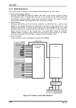
2.3.11 Paper Jam Sensor
This printer is equipped with the paper jam sensor mechanism which consists of the
magnetized roller attached to the same shaft for the sub loading roller assembly and the
sensor (hall element) located beside the rear paper sensor. Having no contact with the
loading drive roller assembly, the magnetized roller rotates independently along paper.
Table 2-20 shows the paper jam sensor specification.
Table 2-20. Paper Jam Specification
Detecting element
Hall element
Outputs
In 1 channel, TTL level
Power supply voltage
5 VDC
±
5%
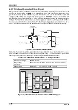
P A 7
P a p e r F e e d D r i v e R o l l e r A s s e m b l y
P a p e r
P a p e r J a m S e n s o r
( H a l l S e n s o r )
P J A M
M a g n e t i z e d R o l l e r
C P U
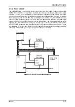
Figure 2-23. Paper Jam Sensor Block Diagram
The CPU reads the signal output directly from the paper jam sensor for each step (1/216
inch / step). If the current signal condition is the same as the previous one, it indicates the
status that the magnetized roller is not rotating, which is considered paper jam. When the
printer detects that condition continuously for the specified numbers of the output signals, it
indicates the paper jam error, and enters non-printing status. The paper jam signal
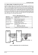
conditions for normal state and paper jam state are shown in Figure 2-24.
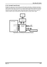
C u r r e n t l y d e t e c t e d c o n d i t i o n
P r e v i o u s l y d e t e c t e d c o n d i t i o n
N o r m a l P a p e r F e e d i n g C o n d i t i o n
P a p e r J a m C o n d i t i o n
Figure 2-24. Paper Jam Sensor Signals
Paper jam detection starts after each paper loading motion regardless of the paper feed
direction. However, the sensor ignores the pulse output while the paper feed direction is
changed.
Summary of Contents for DLQ-3000 Minerva+
Page 1: ...EPSON 24 PIN DOT MATRIX PRINTER EPSON DLQ 3000 SERVICE MANUAL SEIKO EPSON CORPORATION 4008259 ...
Page 5: ...v REVISION SHEET Revision Issued Data Contents Rev A August 21 1997 First Release ...
Page 61: ...2 3 12 Other Sensor Circuits 2 31 ...
Page 160: ...Chapter 6 Maintenance 6 1 Maintenance 6 1 6 1 1 Lubrication and Adhesion 6 1 ...
Page 171: ...DLQ 3000 Rev A A 6 ...
Page 172: ...Appendix Rev A A 7 A 2 Circuit Diagrams Figure A 2 C210 MAIN Board Circuit Diagram 1 2 ...
Page 173: ...DLQ 3000 Rev A A 8 ...
Page 174: ...Appendix Rev A A 9 Figure A 3 C210 MAIN Board Circuit Diagram 2 2 ...
Page 175: ...DLQ 3000 Rev A A 10 ...
Page 177: ...DLQ 3000 Rev A A 12 Figure A 5 C124 PSB Board Circuit Diagram ...
Page 180: ...Appendix Rev A A 15 Figure A 8 C210 MAIN Board Component Layout 2 2 ...
Page 181: ...DLQ 3000 Rev A A 16 Figure A 9 C124 PSB Board Component Layout ...
Page 182: ...Appendix Rev A A 17 Figure A 10 C124 PSE Board Component Layout ...
Page 189: ...EPSON SEIKO EPSON CORPORATION ...