


DLQ-3000+
Rev. A
3-10
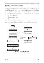
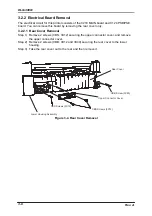
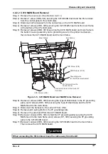
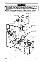
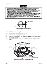
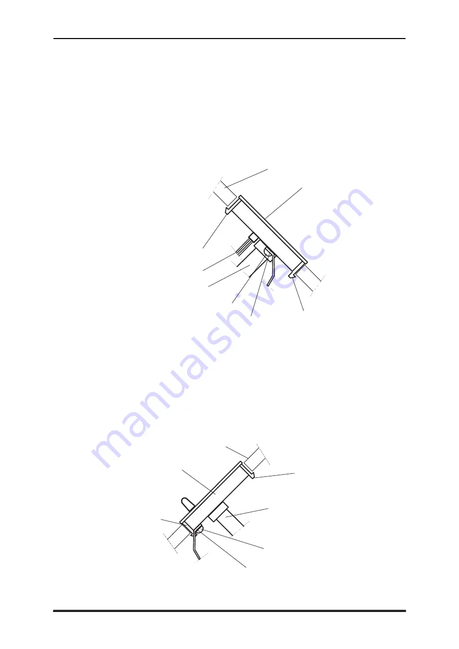
3.2.3 Control Panel Removal
Step 1) Open the printer cover assembly.
Step 2) Insert your hand to the back of the panel and release the hooks securing the
control panel to the upper housing assembly. Then Remove the control panel along
with the harnesses.
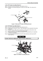
Step 3) Remove 1 screw fixing the FG terminal (red head side) of the harness to the
control panel. Then remove the FG terminal.
Step 4) Disconnect the harnesses for the cover open sensor and the control panel from the
connectors on the control panel board to remove the control panel from the printer.
C o n t r o l P a n e l
H o o k
C o v e r O p e n S e n s o r H a r n e s s
F i x i n g S c r e w
U p p e r H o u s i n g A s s e m b l y
H o o k
F G T e r m i n a l
H a r n e s s f o r t h e c o t r o l p a n e l
Figure 3-8. Control Panel Removal
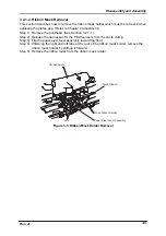
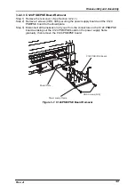
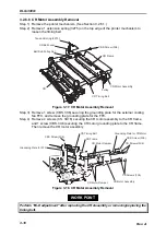
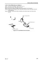
3.2.4 Adjust Switch Removal
Step 1) Open the printer cover assembly.
Step 2) Insert your hand to the back of the adjust switch (Refer to Figure 3-10 for location.),
and release 2 hooks fixing the adjust switch to the upper housing assembly. Then
remove the adjust switch along with the harness for the adjust switch and the FG
terminal.
Step 3) Remove 1 screw fixing the FG terminal to the adjust switch. Then remover the FG
terminal from the adjust switch.
U p p e r H o u s i n g A s s e m b l y
A d j u s t S w i t c h
H o o k
H a r n e s s
F i x i n g s c r e w
H o o k
F G T e r m i n a l
Figure 3-9. Adjust Switch Removal
Summary of Contents for DLQ-3000 Minerva+
Page 1: ...EPSON 24 PIN DOT MATRIX PRINTER EPSON DLQ 3000 SERVICE MANUAL SEIKO EPSON CORPORATION 4008259 ...
Page 5: ...v REVISION SHEET Revision Issued Data Contents Rev A August 21 1997 First Release ...
Page 61: ...2 3 12 Other Sensor Circuits 2 31 ...
Page 160: ...Chapter 6 Maintenance 6 1 Maintenance 6 1 6 1 1 Lubrication and Adhesion 6 1 ...
Page 171: ...DLQ 3000 Rev A A 6 ...
Page 172: ...Appendix Rev A A 7 A 2 Circuit Diagrams Figure A 2 C210 MAIN Board Circuit Diagram 1 2 ...
Page 173: ...DLQ 3000 Rev A A 8 ...
Page 174: ...Appendix Rev A A 9 Figure A 3 C210 MAIN Board Circuit Diagram 2 2 ...
Page 175: ...DLQ 3000 Rev A A 10 ...
Page 177: ...DLQ 3000 Rev A A 12 Figure A 5 C124 PSB Board Circuit Diagram ...
Page 180: ...Appendix Rev A A 15 Figure A 8 C210 MAIN Board Component Layout 2 2 ...
Page 181: ...DLQ 3000 Rev A A 16 Figure A 9 C124 PSB Board Component Layout ...
Page 182: ...Appendix Rev A A 17 Figure A 10 C124 PSE Board Component Layout ...
Page 189: ...EPSON SEIKO EPSON CORPORATION ...