


DLQ-3000+
Rev. A
3-24
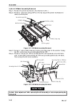
CS board assembly can be removed without removing the CR from the printer
mechanism. In case you omit Step 2 (CR removal), note the followings:
•
•
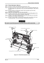
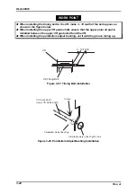
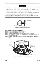
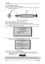
When removing the CS board assembly, note the direction in which the cutout
part of the cam faces. Set the cam as shown in Figure 3-31 so that it is not
damaged by the photo-coupler in the CS board assembly.
•
•
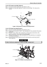
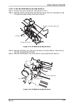
Inside the ribbon cartridge holder, there is a gear train used for ribbon feed and
color shift. Since the gears in the gear train tend to disengage easily, do not
touch the gear train when removing the ribbon cartridge holder.
When installing the ribbon cartridge holder, set the CS cam with the cutout side
facing to the sensor.
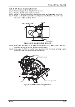
C S B o a r d A s s e m b l y
C S C a m
Figure 3-31. Removing The CS Cam
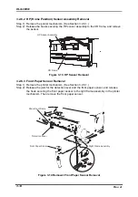
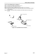
3.2.6.14 PEW Sensor Assembly Removal
Step 1) Remove the printhead. (See Section 3.2.1.1.)
Step 2) Remove the CR. (See Section 3.2.6.12.)
Step 3) Remove the ribbon cartridge holder. (See Section 3.2.6.13, Step 4.)
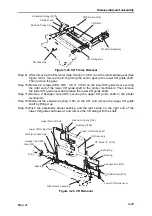
Step 4) Disconnect harnesses for the right and left PEW sensors from the connectors on
the CS board assembly.
Step 5) Remove 2 screws (CBS, 2.5 X 5) securing the PEW sensors to the mask ribbon
holder.
Left PEW
Sensor Assembly
CBS Screws (M2.5X5)
Connctor Cables for the
PEW Sensor Assemblies
Right PEW
Sensor Assembly
Ribbon Mask Holder
Figure 3-32. PEW Sensor Assembly Removal
CAUTION
Summary of Contents for DLQ-3000 Minerva+
Page 1: ...EPSON 24 PIN DOT MATRIX PRINTER EPSON DLQ 3000 SERVICE MANUAL SEIKO EPSON CORPORATION 4008259 ...
Page 5: ...v REVISION SHEET Revision Issued Data Contents Rev A August 21 1997 First Release ...
Page 61: ...2 3 12 Other Sensor Circuits 2 31 ...
Page 160: ...Chapter 6 Maintenance 6 1 Maintenance 6 1 6 1 1 Lubrication and Adhesion 6 1 ...
Page 171: ...DLQ 3000 Rev A A 6 ...
Page 172: ...Appendix Rev A A 7 A 2 Circuit Diagrams Figure A 2 C210 MAIN Board Circuit Diagram 1 2 ...
Page 173: ...DLQ 3000 Rev A A 8 ...
Page 174: ...Appendix Rev A A 9 Figure A 3 C210 MAIN Board Circuit Diagram 2 2 ...
Page 175: ...DLQ 3000 Rev A A 10 ...
Page 177: ...DLQ 3000 Rev A A 12 Figure A 5 C124 PSB Board Circuit Diagram ...
Page 180: ...Appendix Rev A A 15 Figure A 8 C210 MAIN Board Component Layout 2 2 ...
Page 181: ...DLQ 3000 Rev A A 16 Figure A 9 C124 PSB Board Component Layout ...
Page 182: ...Appendix Rev A A 17 Figure A 10 C124 PSE Board Component Layout ...
Page 189: ...EPSON SEIKO EPSON CORPORATION ...