Replacing SA7x FRUs
7.4 TB2 Removal and Installation
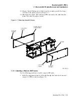
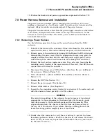
Figure 7–5 Removing TB1
SLOTTED
HOLE
SLOTTED
HOLE
TRANSITION
BOARD 2
TRANSITION
BOARD 1
FRAME
HOLE FOR TB1
RIGHT POSITION
HOLE FOR TB1
LEFT POSITION
J1 40-PIN
CABLE
J2 40-PIN
CABLE
CXO-2612A
7.4.2 Installing Transition Board 2
Use the following procedure to install TB2:
1. Align the replacement TB2 and press it into place, using the four plastic tabs.
Note
The outer holes in each corner of TB2 are for tooling purposes only. Do
not use these holes for installing TB2.
2. Reconnect the eight cables to TB2.
3. Slide the enclosure frame back into the cabinet and secure it in place with the
four mounting screws.
4. If applicable, retract the cabinet stabilizer foot.
5. Reinstall the OCP. (See Section 7.3.)
6. Perform the checkout and power-up procedures explained in Section 7.10.
7–8 Replacing SA7x FRUs


