


Replacing SA7x FRUs
7.3 OCP Removal and Installation
CAUTION
Do not bend the alignment or connector pins when reinstalling the OCP.
The panel should go into place without being forced.
3. Perform the checkout and power-up procedures explained in Section 7.10.
7.4 TB2 Removal and Installation
Transition board 2 (TB2) is located behind TB1 inside the enclosure.
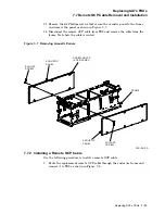
7.4.1 Removing Transition Board 2
Use the following procedure to remove TB2:
1. Take all of the drives in the enclosure off line and release the Run switches
to spin down the drives. Wait until all Ready lamps are off. (Refer to
Section 4.4.)
2. Remove power to the enclosure by turning off the Master On/Off switch.
(Refer to Figure 7–3.)
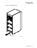
3. If the cabinet has a cabinet stabilizer foot installed, extend it. (Refer to
Figure 7–2.)
4. Remove the OCP. (See Section 7.3.)
5. Loosen the four mounting screws (located at each corner of the enclosure) and
slide the enclosure frame partially out of the cabinet. Pull out only enough of
the frame to allow access to TB2.
WARNING
Be careful when pulling out the enclosure frame for access to its internal
components. A stop mechanism in the chassis locks the frame at a point
that allows access to the transition boards and the fan assembly. This
stop mechanism locks the chassis so that the frame is three-quarters of
the way out of the chassis. If you release this stop, nothing prevents the
frame from being pulled completely free of the chassis.
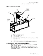
6. Disconnect the eight cables connected to TB2. (See Figures 7–4 and 7–5.)
7–6 Replacing SA7x FRUs


