Replacing SA7x FRUs
7.8 Power Harness Removal and Installation
WARNING
Releasing the chassis latch allows the frame to be removed from the
chassis for this operation. Be prepared to take the weight of the frame
when it comes free of the chassis. Have a work space ready to put the
frame on after it is removed.
11. Pull the frame free of the chassis by reaching into the frame and grasping the
sheet metal in front of the fan. Set the frame on an antistatic work surface.
12. Lay the frame on either side and remove one of the two acoustic panels.
Remove the six Phillips screws that secure the acoustic panel to the frame,
and remove the panel. (Refer to Figure 7–7.)
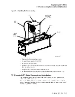
13. Turn the frame upside down, as shown in Figure 7–9.
14. Remove the Phillips screw located on either side of the drive power switches
(two screws). This allows you to remove the protective covering for the drive
power switches.
15. Remove the protective covering for the drive power switches. This exposes
the cabling from the power harness to the drive power switches.
16. Remove the two Phillips screws holding the power supply connector to the
frame.
17. Tilt the power supply connector so that it can be removed from the bracket,
and disconnect it. The connector cannot be removed unless it is tilted.
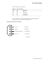
18. Carefully disconnect all single and pigtail black and orange wires from each
of the drive power switch terminals. Each drive power switch wire is labeled
according to its intended switch. Wires in each group are color coded:
• Single black is the SW A wire to TB2.
• Orange is the LED wire from the power supply to the associated drive
power indicator.
• The two pigtail black wires are returns.
19. Note how the power harness is routed, and then remove the power harness
from all disk drive positions.
7.8.2 Installing a Power Harness
Use the following procedure to install the power harness.
1. Route the replacement cable in the same manner as the original cable, as
shown in Figure 7–9.
2. Connect the power supply connector to the power supply bracket by first
tilting the connector until it is flush against the bracket. Secure the power
supply connector with the two Phillips screws.
3. Connect all single and pigtail black and orange wires to all drive power
switches (observing proper disk drive position).
7–16 Replacing SA7x FRUs


