


SA7x Technical Description
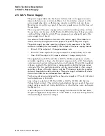
2.5 SA7x Power Supply
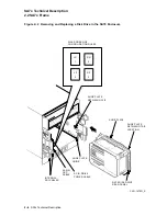
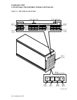
Figure 2–6 SA7x Enclosure Rear Panel and Power Supply
PORT A
SILK SCREEN
PORT B
SILK SCREEN
SDI INTERFACE
CONNECTOR
PORT A
SDI INTERFACE
CONNECTOR
PORT B
REAR
BULKHEAD
REAR
COVER
MOUNTING
SCREW
MOUNTING
SCREW
OVER-
TEMPERATURE
INDICATOR
(BEHIND PANEL)
LINE VOLTAGE
SELECTOR SWITCH
(BEHIND PANEL)
MASTER
ON/OFF
SWITCH
LINE VOLTAGE
CONNECTOR
POWER
SUPPLY
TABS
CXO-2658C
The following discussion is based on the block diagram in Figure 2–7.
The input voltage is applied to two paths. One path consists of the internal
regulated power supply which provides all internal operating voltages for the
power supply. The shutdown signal comes from the power supply’s output voltage
and environmental monitoring circuits. This signal turns off the +10 Vdc output
of the internal supply to shut down the entire power supply.
The second path for the input voltage is to a +300 Vdc unregulated supply. The
output of this supply is applied to +12.6 Vdc and +5.6 Vdc switching-regulated
supplies. The regulator outputs then go to individual regulators to provide
the final +5.1 Vdc and +12.1 Vdc voltages for each disk drive. There are no
adjustments on the power supply outputs.
The fan re12.6 Vdc directly from the output of the switching regulator.
SA7x Technical Description 2–11


