SA7x Internal Cabling
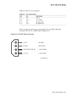
Figure A–3 is a block diagram of the OCP to transition board assembly to drive
cabling.
The operator control panel (OCP) assembly contains the OCP module and two
LED modules. Left and right LED modules route numeric display information
and the ready light signal between the LED modules and the OCP. Left and
right front and rear LED functions are controlled by the respective modules.
Because the OCP assembly is a field replaceable unit (FRU), the LED modules
are replaced with the OCP. Therefore, connectors between the OCP and the LED
modules are not shown in this section.
Figure A–3 OCP to Transition Board Assembly to Disk Drive Cabling
LR
RR
J3
J3
J-1
J-2
LF
J3
RF
J3
J-6
J-4
J2
J3
J8
J5
TB2
54-19015-01
OCP
70-25696-01
J3
J-1
J-4
TB1
54-19171-01
PLUG-IN CONNECTOR
70-26254-02
70-26254-01
70-26254-01
17-02717-01
CXO-2598A
Note
The latest version of transition board 2 is Revision F03.
A–4 SA7x Internal Cabling


