SA7x Technical Description
2.4 SA7x OCP and Transition Board Assembly
2.4 SA7x OCP and Transition Board Assembly
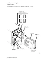
The OCP consists of a plastic bezel, an electronic emissions (EMI) shield, a
plastic retainer, and a three-module circuit board set. The OCP assembly is
designed to be a one-piece field replaceable unit (FRU). An associated transition
board assembly is fastened to the SA7x frame. The OCP connects to TB1 with a
96-pin male connector and two clip/bullet fasteners (located on either side of the
connector). TB2 interfaces to TB1 through two ribbon cables.
The OCP communicates through the transition board assembly with up to four
RA7x disk drives. Each OCP control set contains the following, as shown in
Figure 2–4:
• Run switch
• Fault/Set No. switch
• Write Protect switch
• Port A switch
• Port B switch
• Unit No. display
Note
The OCP Unit Selector switch puts the OCP into the unit select mode.
This unit select function allows you to change any drive unit number
without interrupting the operation of the remaining disk drives. The unit
numbers may be either from 000 to 255 or from 000 to 999, depending on
the revision level of TB2.
The OCP can be installed in either the right or left side of the enclosure frame,
depending upon the enclosure’s position in the cabinet. A block diagram of the
OCP and transition board assembly is shown in Figure 2–5.
The transition board assembly consists of two individual boards: TB1 and TB2.
TB2 transfers signals from each of the four disk drives through two 40-pin cables
to TB1. TB1 transfers the drive signals through the single OCP connector to the
OCP.
Circuits on TB2 determine the power up/down protocol for the disk drives. The
protocol is derived through comparator circuits that monitor the ACOK line and
individual drive power switch status on one input, and a reference voltage on the
other input. The comparator outputs provide individual ACOK signals for each
drive and provide dc control from the power supply to the disk drives through the
drive power switches. In the power supply, these control signals are the on/off
controls for the individual regulators that provide the power for each disk drive.
Each of the drive power switches is a grounded circuit when the switch is off;
turning the power switch on removes the ground and signals status back to TB2.
TB1 monitors the incoming ambient air temperature and sends a control signal to
a driver circuit in the fan assembly to operate in low-speed mode if the air inside
the enclosure is within operating limits. If the air temperature rises above preset
limits, the control signal is removed by TB1 and the fan changes to high-speed
operation.
2–6 SA7x Technical Description


