8 Application Instructions API 100-149
DVP-PLC Application Manual
8-60
heating environment” to enhance the speed to reach SV. On the contrary, when the user finds that the control is
too fast or with too many fluctuations, select “fast heating environment” to slow down the control speed.
When bit2 ~ bit5 of
S
3
+1 are all set as 1 or more than 1 environments are designated, FTC instruction will check
from bit2 to bit 5 in order and enable the function that has been set as 1. The parameter can be modified during
the control.
4.
Example 1:
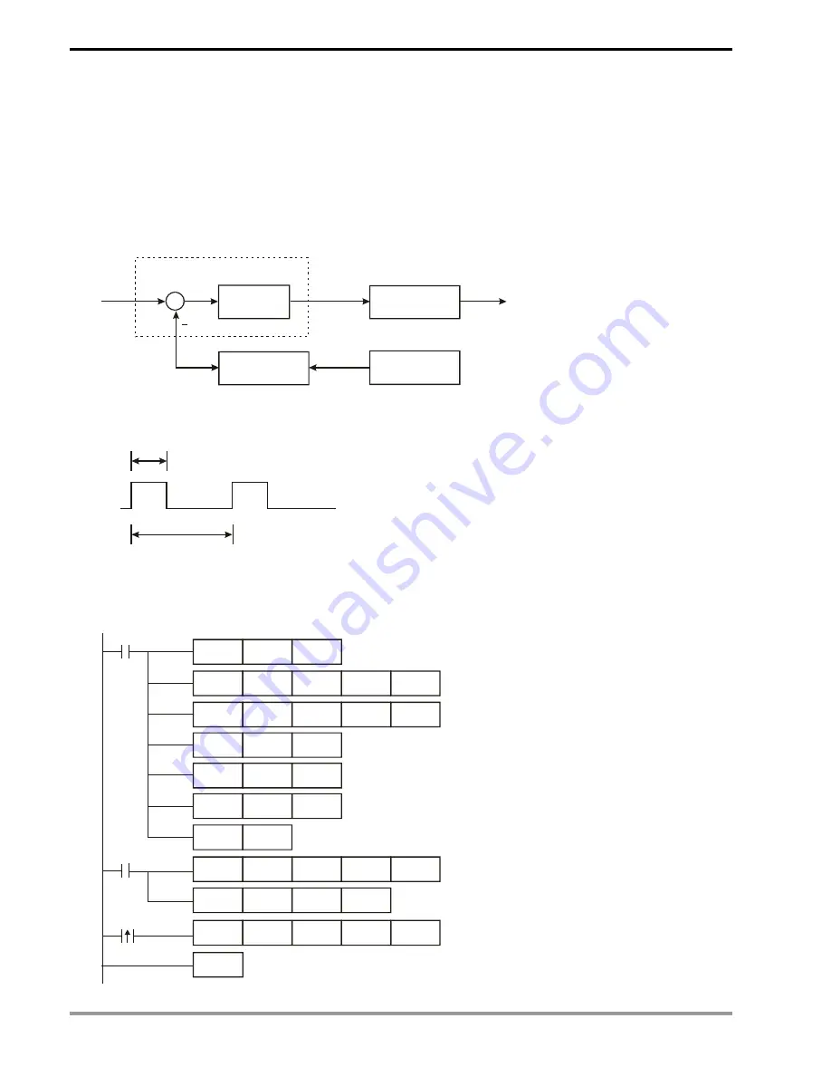
control diagram
Fuzzy
Controller
FTC
SV
D10
D22
MV
Y0
D11
PV
+
e
PT Module
GPWM Program
Temperature
Sensor
Output D22 (MV) of FTC instruction is the input D22 of GPWM instruction, as the duty cycle of ajustable pulses.
D30 is the fixed cycle time of pulses. See below for the timing diagram of Y0 output.
D22
D30
Y0
Assume parameter settings: D10 = K1,500 (target temperature), D12 = K60 (sampling time: 6 secs.), D13 = K8
(bit3=1), D30 = K6,000 (=D12*100)
The example control program is indicated as:
M1002
MOV
K1500
D10
TO
K0
K2
K2
K1
FROM
K0
K6
D11
K1
MOV
K60
D12
MOV
K8
D13
MOV
K6000
D30
SET
M1
M1
FTC
D10
D11
D12
D22
GPWM
D22
D30
Y0
M1013
FROM
K0
K6
D11
K1
END
Summary of Contents for DVP-PLC
Page 1: ...PLC PLC...
Page 28: ...1 Basic Principles of PLC Ladder Diagram DVP PLC Application Manual 1 24 MEMO...
Page 192: ...4 Step Ladder Instructions DVP PLC Application Manual 4 22 MEMO...
Page 472: ...8 Application Instructions API 100 149 DVP PLC Application Manual 8 70 MEMO...
Page 574: ...9 Application Instructions API 150 199 DVP PLC Application Manual 9 102 MEMO...


