7 Application Instructions API 50-99
D V P - P L C A P P L I C AT I O N M A N U A L
7-112
b) PID instruction can only be used once in ES/EX/SS (v5.6 and below) series MPU. There is no limitation on
the times of using PID instruction in ES/EX/SS (v5.7 and above) series and SA/SX/SC/EH/EH2/SV series
MPU.
c)
S
3
+ 3 of ES/EX/SS (v5.7 and below), SA/SX/SC (v1.1 and below) and EH (v1.0 and below) series MPU can
only be the value within 0 ~ 30,000.
d) There are a lot of circumstances where PID instruction can be applied; therefore, please choose the control
functions appropriately. For example, when you select parameter auto-tuning for the temperature (
S
3
+ 4 =
K3), you cannot use it in a motor control environment in case improper control may occur.
e) When you adjust the three main parameters, K
P
, K
I
and K
D
(
S
3
+ 4 = K0 ~ K2), you have to adjust K
P
first
(according to your experiences) and set K
I
and K
D
as 0. When you can roughly handle the control, you then
adjust K
I
(increasingly) and K
D
(increasingly) (see example 4 below for how to adjust). K
P
= 100 refers to
100%, i.e. the gain of the error is 1. K
P
< 100% will decrease the error and K
P
> 100% will increase the error.
f) When you select the parameter exclusively for temperature control (
S
3
+ 4 = K3, K4), it is suggested that you
store the parameter in D register in the latched area in case the automatically adjusted parameter will
disappear after the power is cut off. There is no guarantee that the adjusted parameter is suitable for every
control. Therefore, you can modify the adjusted parameter according to your actual need, but it is suggested
that you modify only K
I
or K
D
.
g) PID instruction can to work with many parameters; therefore please do not randomly modify the parameters
in case the control cannot be executed normally.
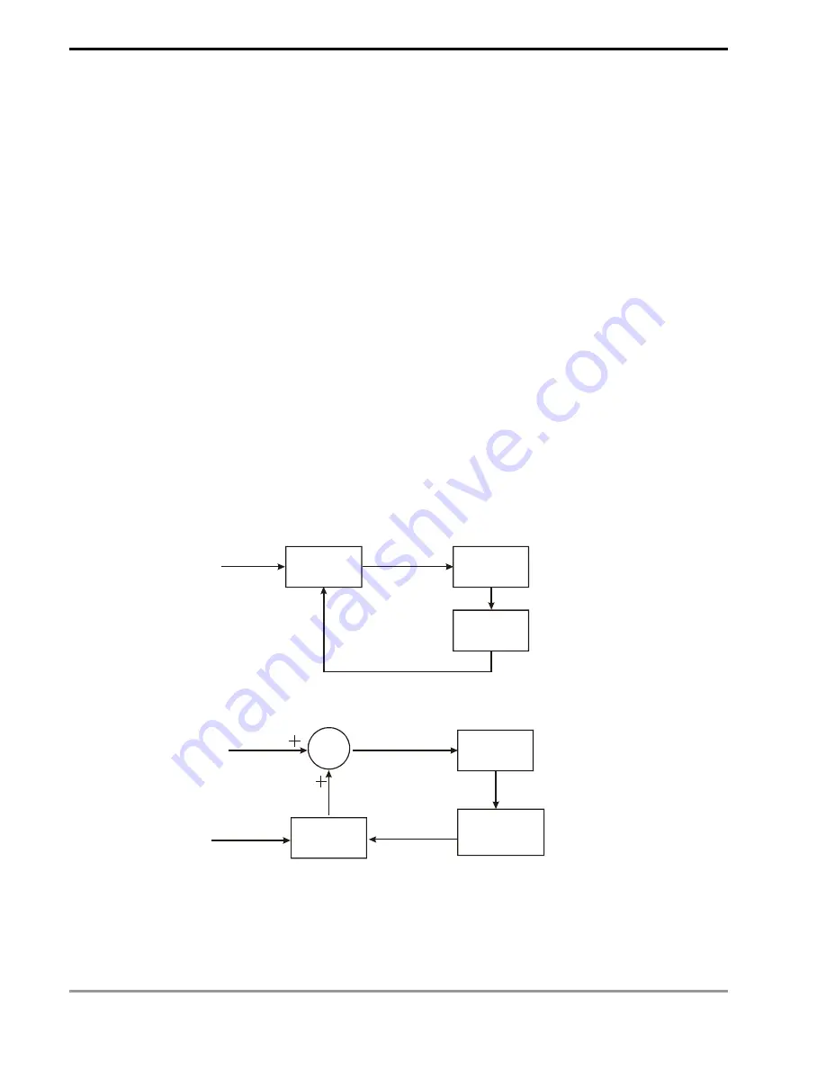
Example 1:
Diagram of using PID instruction in position control (
S
3
+ 4 = 0)
PID
MV
Encoder
PV
Position instruction
(SV)
Controlled
device
Example 2:
Diagram of using PID instruction with AC motor drive on the control (
S
3
+ 4 = 0)
PID
S+MV
Speed instruction (S)
Acceleration/deceleration
instruction (SV)
Acceleration/deceleration
output (MV)
Actual acceleration/
deceleration speed
(PV = S - P)
AC motor
drive
Speed
detection
device (P)
Summary of Contents for DVP-PLC
Page 1: ...PLC PLC...
Page 28: ...1 Basic Principles of PLC Ladder Diagram DVP PLC Application Manual 1 24 MEMO...
Page 192: ...4 Step Ladder Instructions DVP PLC Application Manual 4 22 MEMO...
Page 472: ...8 Application Instructions API 100 149 DVP PLC Application Manual 8 70 MEMO...
Page 574: ...9 Application Instructions API 150 199 DVP PLC Application Manual 9 102 MEMO...


